Skeletyl Keyboard Build
Motivation for this project
So back in November 2022 there was a giveaway contest run by kbd.news. I entered and was one of the winners and we got a choice of various discount coupons, so I requested a discount over at bastardkb. I was very curious about the flexible PCBs Quentin uses in his low-profile dactyl-inspired builds. I had already made a DIY TBK Mini which is his 3x6+3 flavor. I 3D printed the case, glued in kailh choc brown tactile low-profile switches, hand wired the matrix, and used a pair of elite-c microcontrollers. I realize now that I never even blogged about that build. I forget exactly when I did it, but the pertinent takeaway is that it is a pretty great form factor and it was my daily driver for a while just prior to the squeezebox v2112 being ready for action.
After daily driving my Keyboardio Model 100 while traveling this winter, when I got back home I was really missing QMK's combo support and the lower travel of choc switches, so I busted out the tbkmini again. It's very pleasant to type on. My only real issue with this one is I would now prefer linear switches as opposed to the brown tactiles which are in there. They are feeling quite sticky and inconsistent. The other janky part of my tbkmini is I 3D printed a small MCU holder but did not have the modeling skills to make it mount properly to the threaded inserts in the case, so instead I cut out a slot for it and glued in some terrible hacky adapters. It works fine but it's a hack job for sure.
So my hope was to build a skeletyl which would be same basic shape with a few improvements:
- Remove the outer pinky column which is an RSI injury factory. I don't use it anyway, but just get rid of it.
- Use some linear choc silver switches
- Get the fancy flex PCBs so I don't have to hand wire it
- Get the MCU holder so that part is solid and not janky.
The order and the case
So I used the coupon to order the skeletyl kit which has the flex PCBs, MCUs, diodes, screws, threaded inserts, TRRS jacks, etc. But no case, switches, or keycaps. So while traveling and visiting a friend I got access to a 3D printer and cranked out the 2 case tops and bottom parts so those were already done and came out really well. The order was here waiting for me when I got home.
The first build session, first oopsie
I sat down to study the build guide and a few youtube video build vlogs. When I test fit a kailh choc silver switch into the case it fits fine since choc and MX slot into the same size square cutout, but the PCB would not engage. The choc housing does not protrude beyond the bottom of the case and there's no way to mate it into the PCB. I searched around bastardkb for "choc" and was surprised to find that my fears were true: if you build with the flex PCBs, they only support MX switches and not chocs! Oh no! I've seen some clever PCB footprints that support both so it's possible, but even the switch pin through holes are not in the right spot.
I was a bit despondent about this. After a long sigh of "why do I do this keeb life to myself" and some navel gazing, I considered two possible paths forward.
- Research silent linear MX switches with the shortest activation travel and total travel, order them, and use MX for this build
- Hack through it by running tiny sections of wire from the choc switch pins through the PCB through holes.
I thought the choc hack might run into mechanical difficulties actually getting the sections of wire to thread through the PCB through holes when you account for it needing to be mounted into the case while this happens and there might not be any clearance to get tweezers in there to guide the wires through the holes and just might be terribly frustrating.
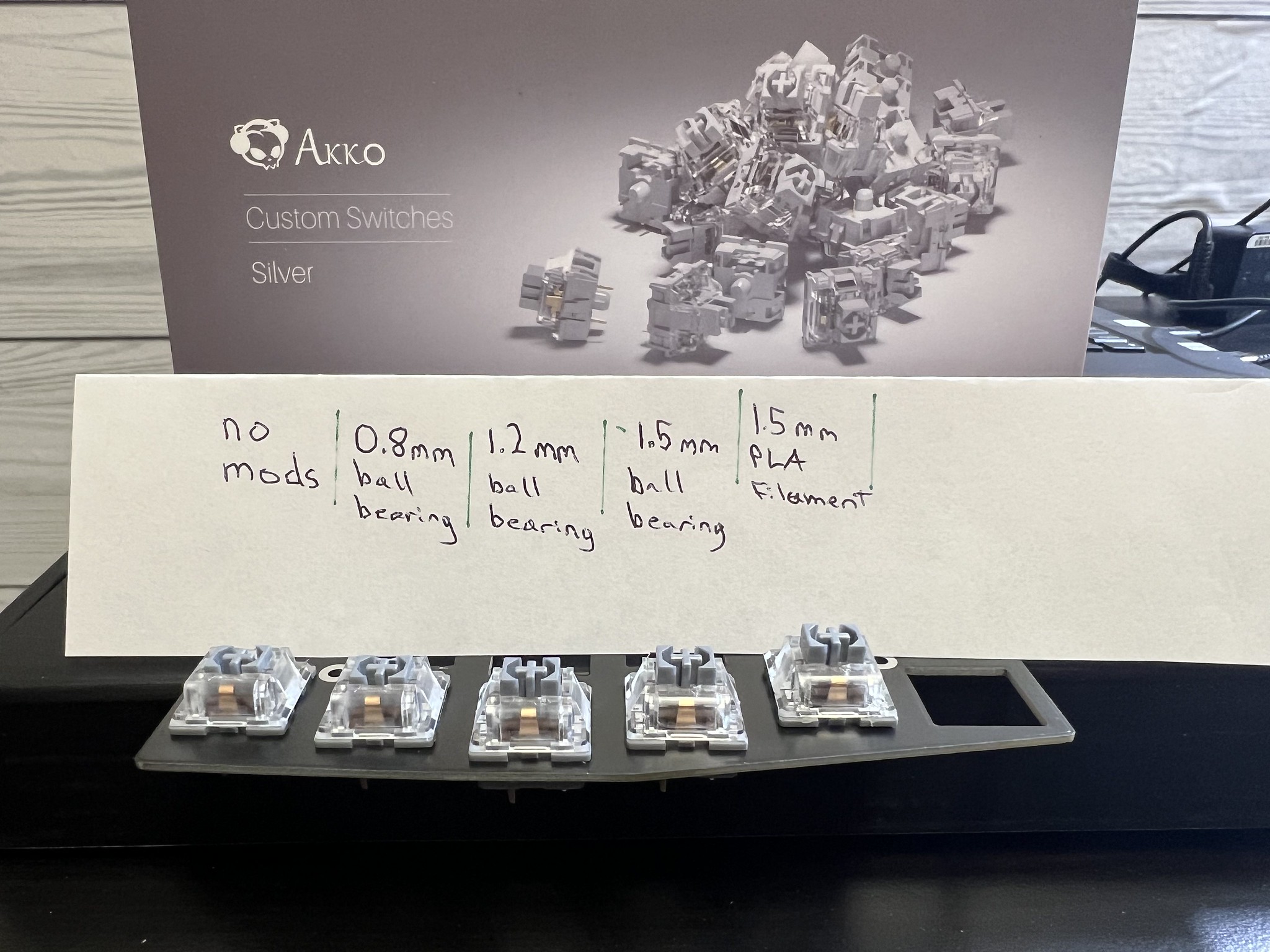
So I asked in my channel on the Absolem Club Discord and someone recommended akko custom silver for short activation travel. So I ordered a box of those sufficient to build this 36-key keyboard.
MX Switch Modification Side Quest
In discord discussions around my fruitless quest for low-travel switches, folks pointed me to both o-rings as a possible mod as well as the ball bearing mod.
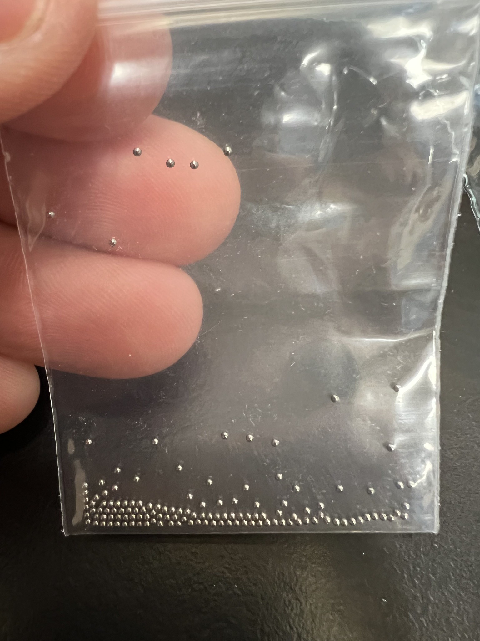
I've never truly grokked the mechanism by which folks claim o-rings work and the whole thing seems dubious, but I ordered sets of ball bearings in 0.8mm and 1.2mm diameters and a bag of o-rings without extensively searching/shopping/understanding the available varieties.
So the build gets paused for a week or so then I proceed with experimental modding to reduce travel.
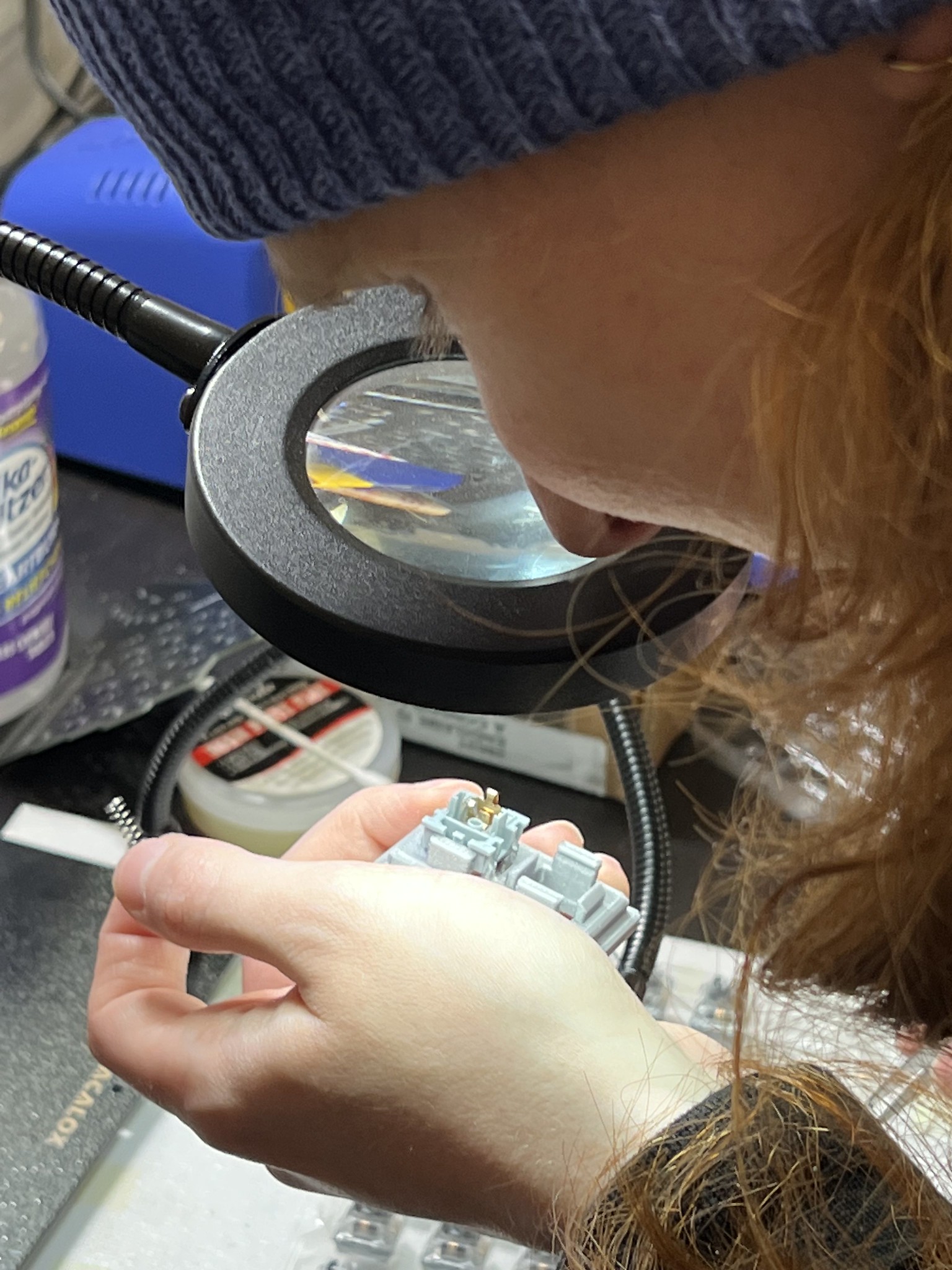
While experimenting with different size ball bearing mods to reduce travel, we didn't have a great test rig set up. I guess ideally you'd have a hotswap MX keyboard at hand and swap in your modded key to do some careful quality control tests. Being low-profile enthusiasts, we have little to no MX gear around here, so our test rig consisted of holding the modded switch in the skeletyl PCB and trying to rotate it where both switch pins would make good contact with the PCB through holes then while not letting that wiggle out of place, try to type. We basically got "it never types" or "it probably types OK" result accuracy.
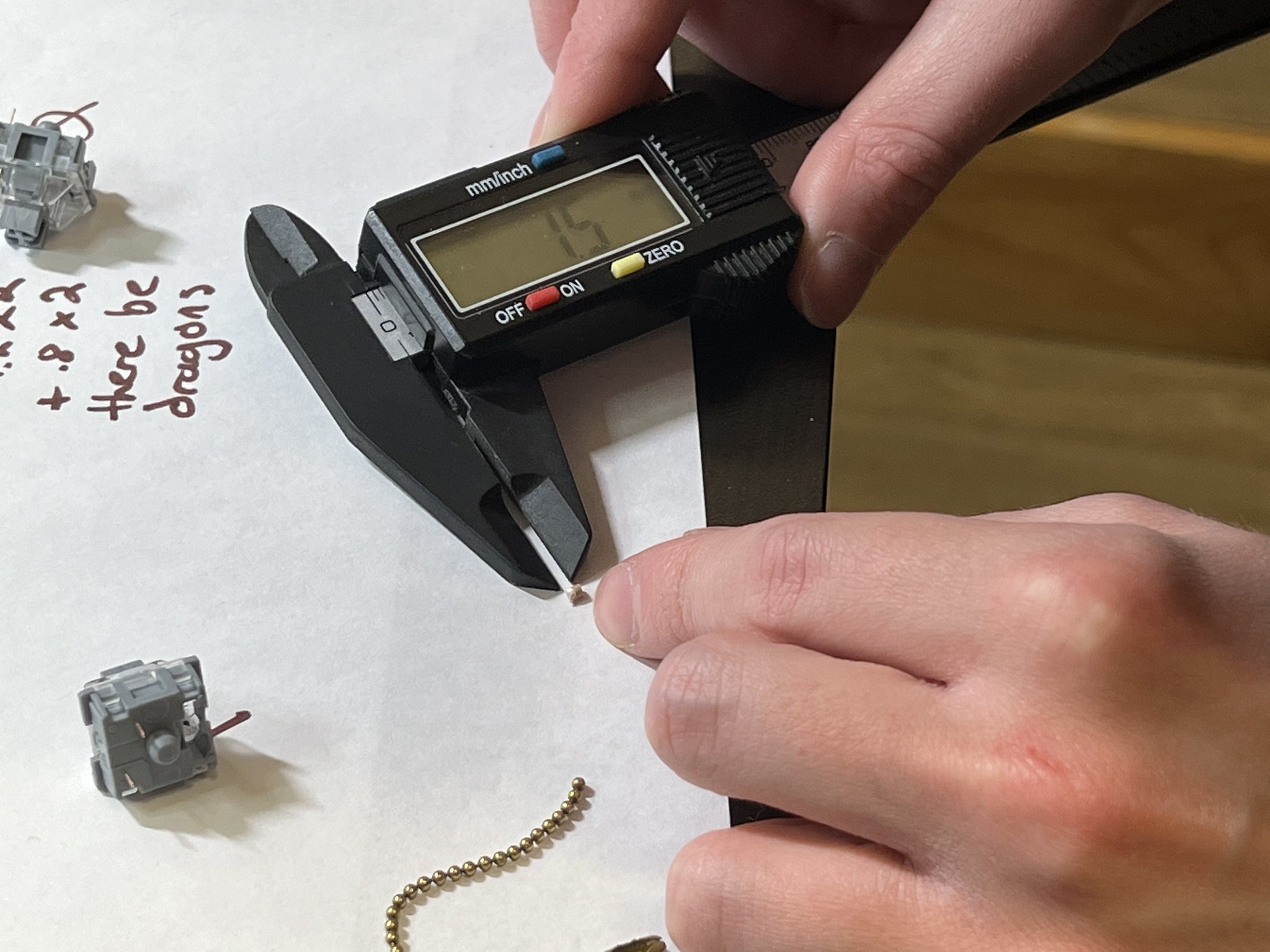
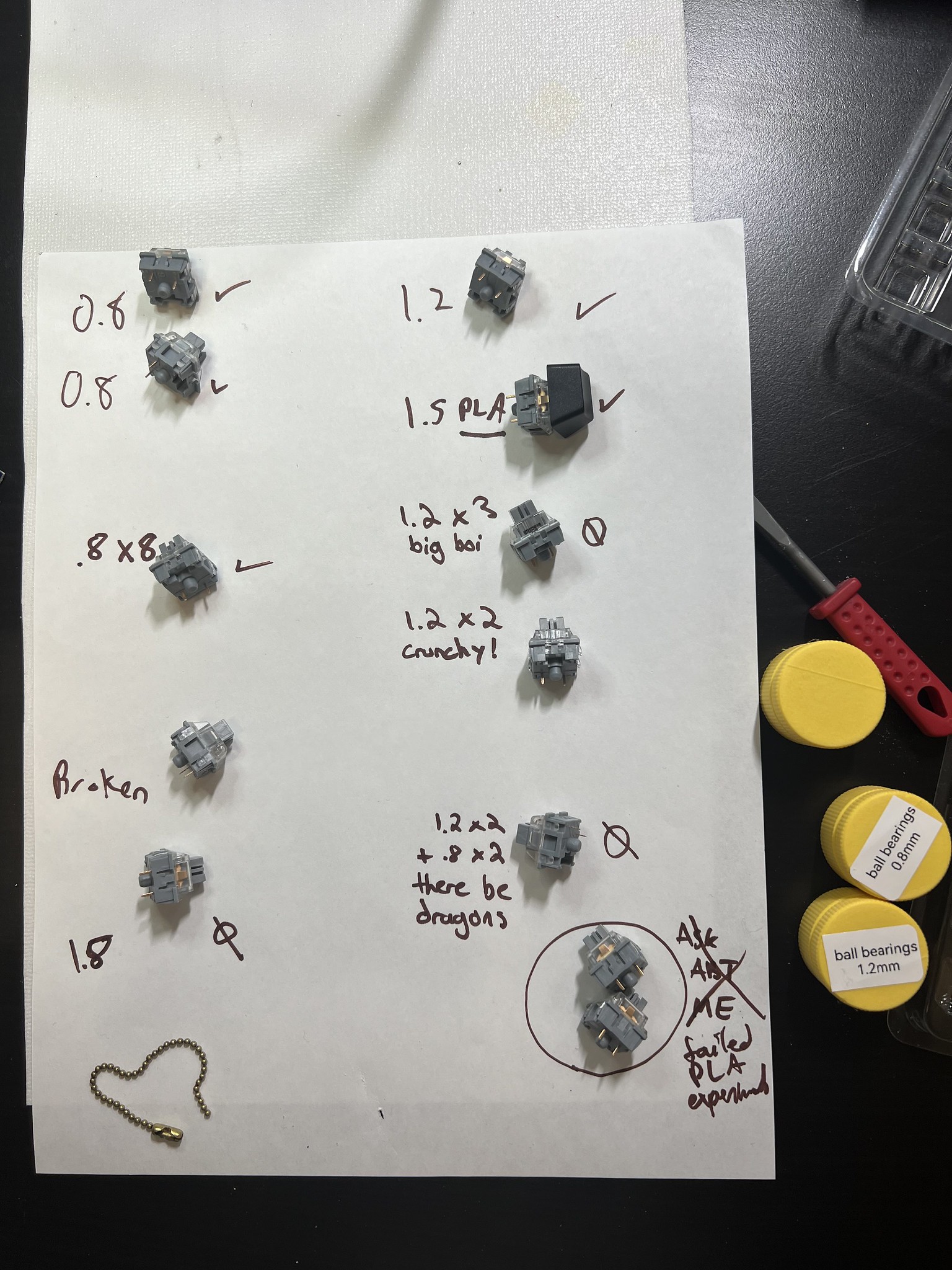
We discovered you can put as many as 8 0.8mm ball bearings in the switch post and still have the switch activate. We tried all the basics and some weird things like combinations of ball bearings of different sizes. The main learning from the first session was that 1.2mm still activated the switch (* footnote spoiler read ahead), so we decided to proceed and order 1.5mm ball bearings even though the original post we were studying said it was too large. Maybe because these akko CS silver switches have a high activation point our were still activating?
We didn't have any 1.8mm ball bearings, but we found the little brass spheres from a keychain were about that size so we tried that and found the switch wouldn't activate. So that was our upper bound.
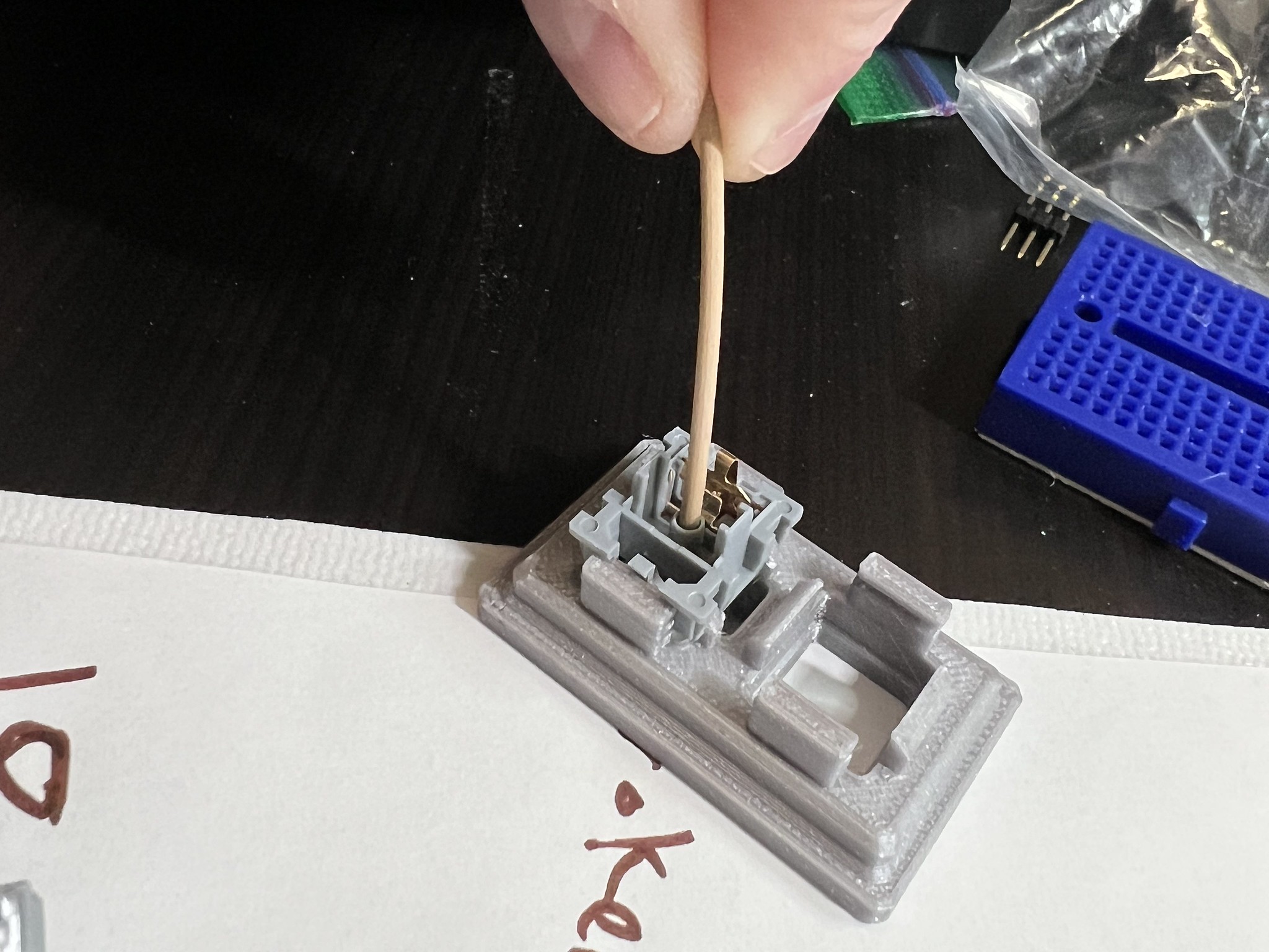
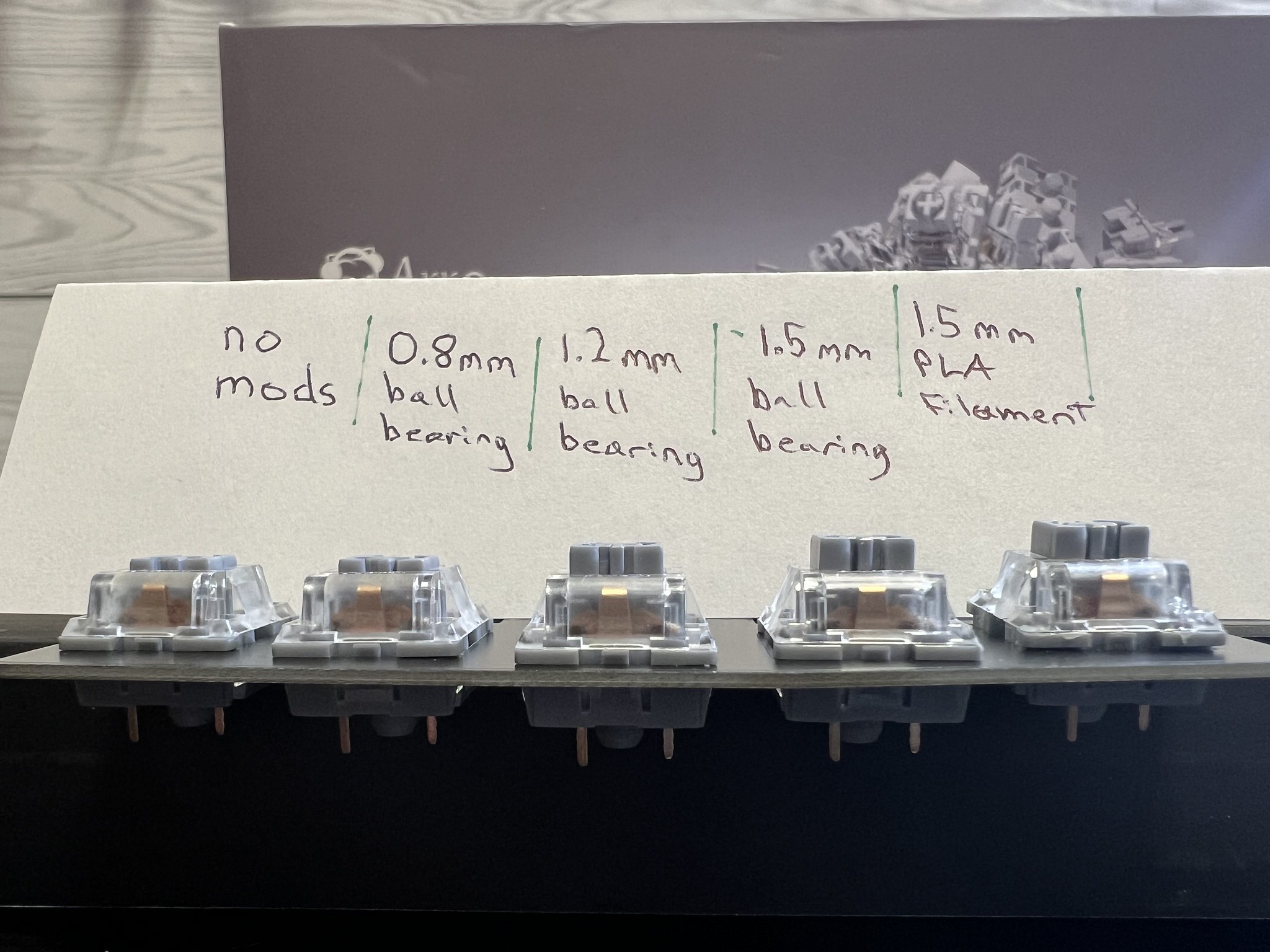
We got a nice shot of the travel reduction of each mod by removing the springs so gravity would leave the stem in the lowest position for the photo. The rightmost switch isn't fully seated into the plate. Sorry about that. I didn't notice until I had already torn down the rig. But the 1.5mm ball bearing and 1.5mm hunk of PLA filament both do exactly the same thing to the stem travel.
Build modded switches into the PCB?
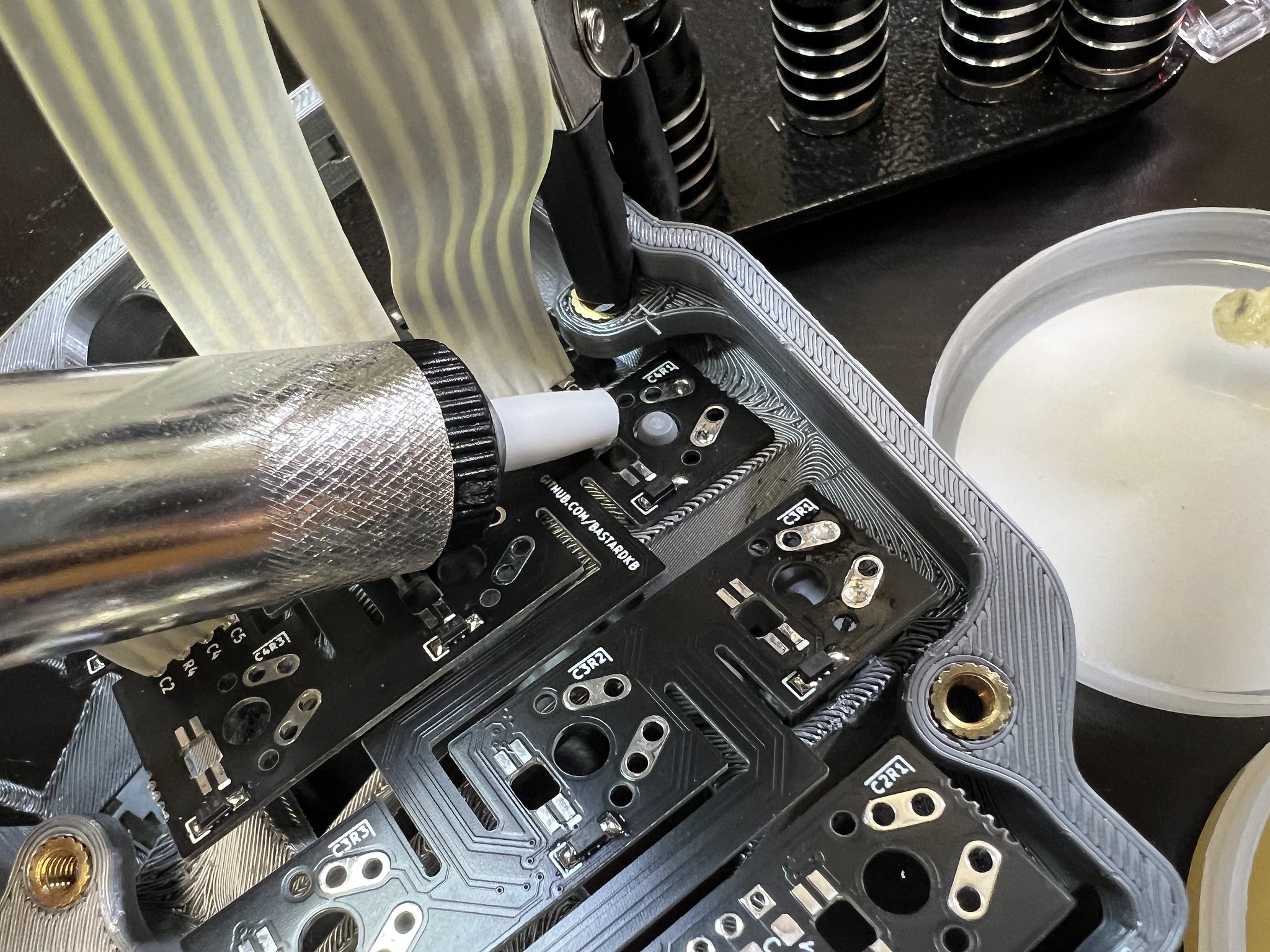
So yesterday we proceeded to insert a modded switch into the skeletyl 3D printed case, bend the flexible PCB into position over the post, and solder the first switch into the case. Once that was done, we had a much more reliable setup from which to carefully test for clean typing.
AC went into production line mode opening switches and preparing to work through a full batch of 18 switches, but I insisted we do a round of careful tests first. It turned out to be the right approach because as we tested, we easily found clear double-press misfires with sometimes as much as like 5% probability. So we kind of panicked a bit and soldered I think 3 total switches in: one stock with no modifications, one with a 1.2mm ball bearing, and one with a 1.5mm ball bearing.
The unmodded switch worked without issue. Both of the modded switches had frequent double-fire errors. I got pretty despondent and felt like all this time researching, ordering, waiting for parts, 3D printing custom tools, etc was a waste. I mean, we learned what doesn't work though, right?
So then I had to desolder the modded switches so we could unmod them. I got them out but desoldering is tricky business.
So next there was like a camera pan to a high overhead shot of me in the lab where this project was supposed to yield a choc skeletyl and instead here I am building with unmodified MX switches with a mile of travel and a super high profile like a pleb. So I decided to just finish the build, play around with vial firmware which I haven't used yet, and try it out. If it's OK for me to type on, it will be in theory less janky than my current daily driver hand wired tbkmini.
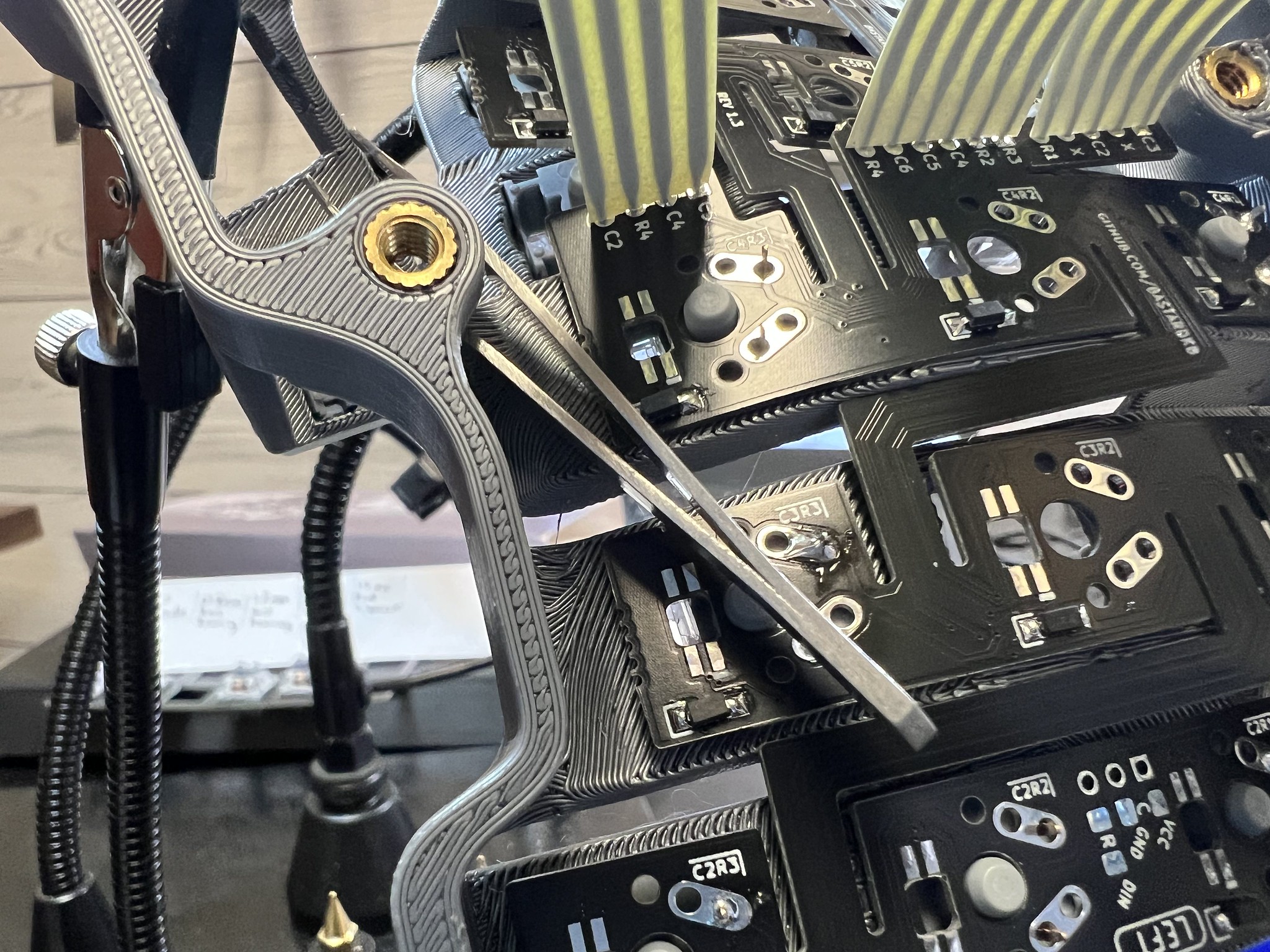
Getting the switches installed, clicked into the "flexible" PCBs and soldered on a skeletyl is hard. Like really hard. Like, it would be easier to hand wire this hard. The "flex" mechanism doesn't really handle the z-axis variation that well. I bent switch pins on a bunch of switches in trying to get the PCB pressed into place.
Eventually I found solutions combining helping hands clamped to the case, and either a tweezer wedged in holding the PCB down or a spring clamp if there is access from the side to place it.
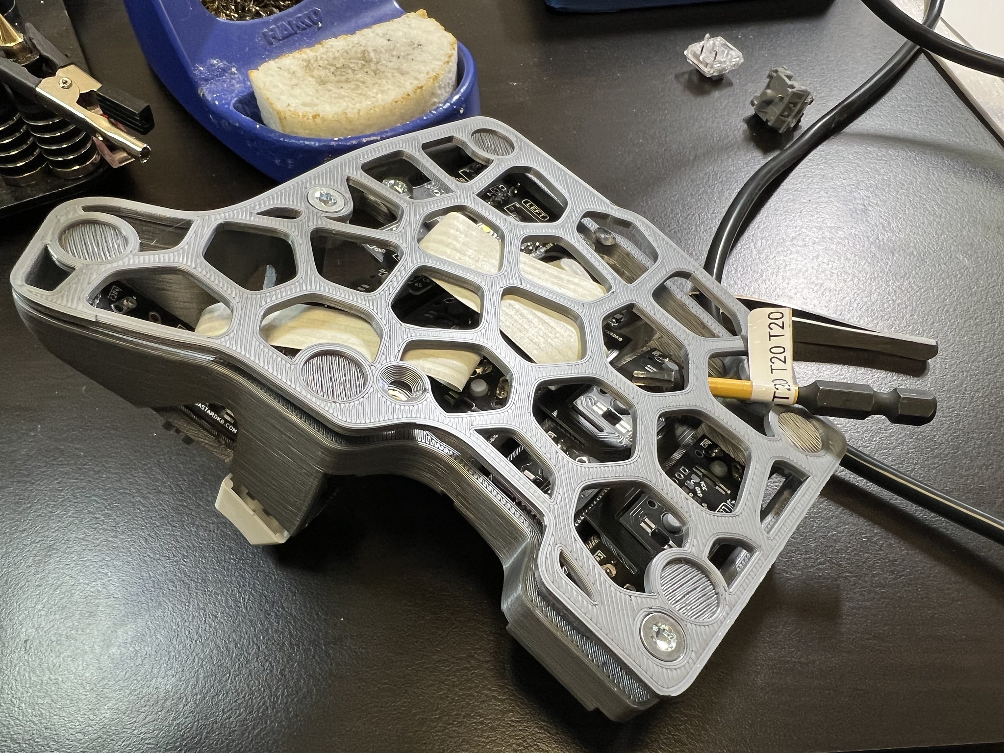
When I got one side finished, I mounted the MCU holder PCB to the case. This was also very tricky to get both ports fully aligned with their holes in the case and both of the threaded inserts exactly below the through holes so the screws can thread in. I eventually got it to work, but this could easily have been 15 minutes of futzing.
When I went to attach the bottom plate, I had another sad trombone moment when I realized I had soldered the ribbon cables to the wrong side of the MCU PCB. I think the electronic connections are still right because the legends lined up, but there's also a chance that the wiring matrix is now messed up and I'll have to adjust the firmware to compensate for that. But in the end, I just bent the ribbon cables a bit closer to the PCB and a bit sharper of an angle than is probably ideal, but the case does now fit and doesn't bulge out at that spot. I could try to fix this before finishing the other half but I think it'll be easier to manage if both halves are symmetric. Plus, I did probably my best ever soldering job on this project and I don't want to mess that up with a bunch of desoldering and resoldering on the ribbon cables.
I went through and finished soldering all of the switches into both halves. When that was done I tested them and of course found that my home row index finger switch was busted, and of course accessing the underside of that one to desolder it requires removing the MCU holder again. So I undid all those bolts, managed to get the switch desoldered and slurp off the excess solder, find a switch from our stack of experiments that I could restore to unmodded operable state, and solder that into place.
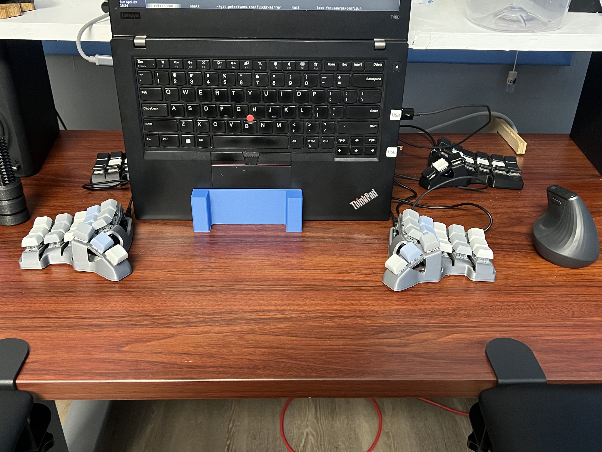
OK so I'm now typing on the new skeletyl build. I threw some MX DSA keycaps on it that we had lying around from the early days when we were trying to build dactyl manuforms. I put some rubber bumper feet on it and connected it to my laptop. I have not used Vial before this and it's very awesome. The keyboard was recognized and kind of to my surprise both halves worked with nothing about the matrix busted (at least if I connect USB to the right hand half).
So I very quickly set up my layers and keymaps and Vial applies them in real time with no flashing which is amazing.
So I've already done 88 WPM on monkeytype. How loud these switches are is going to take some adjustment, but I think it'll be fun to wade into the world of MX true mechanical keyboards for a while at least.