Squeezebox Keyboard v2112
Overview
The Squeezebox Keyboard is a custom-designed ergonomic computer keyboard I have been working on for nearly a year now. The primary design driving factors include:
- Wanting the keys really close together both within a column and across columns
- If there was a nice switch smaller than the Kailh chocs, I'd be interested
- "Home corner" concept for the home row and bottom row taking curvature to an extreme and making a straight-up corner (100 degree angle)
- Each finger can rest on 2 keys and hit either without "moving" by using the fingertip and pad, respectively
- Mechanical tailor fit without many rounds of long and perilous 3D prints
Earlier Prototypes
This post describes my latest fully functional build/prototype. Earlier builds include the original non-tented version from April 2021 and the steeply tented version with magnetic posts on a steel base plate from June 2021.
Review of existing aspects
If you are just seeing this project for the first time, here's a recap of some other things to note about the design.
- No keycaps! Naked switch stems. Kailh choc switches don't need no stinking caps.
- Super tight spacing. Even the pinky can reach all 3 rows without stretching/straining and without having to move the whole arm. I have to move my arm to type the top pinky row on most keyboards I've tried, and for years I pressed that key with my ring finger without consciously realizing it.
- Allow chording the middle and bottom row with a single finger from the home position
- Whether this is really practical with QMK, whose chording support is not that great, is still kind of TBD. A custom firmware with carefully implemented first class support for this might make this a central feature, but as of now I can't yet do it consistently/accurately enough to use it for important stuff.
- Switches can be hot swapped out
- Each finger can be independently finely adjusted in column stagger, splay angle, and height
- Modular design facilitates things like swapping in a different thumb cluster, for example
- Designed around steep tenting split usage
What's new in this version
Slots on the base plate
The primary mechanism of adjustment near/far has been changed to moving the finger columns along a grid of slots in the base plate, which has been custom designed and 3D printed to support this. The previous build used a steel base plate and magnets. That was kind of neat in the arbitrary precision of it and using the same mechanism for both columnar offset (near/far) and splay angle (finger columns like rays emanating from a center point vs 4 parallel lines). However, it was a bit too difficult to get everything in an optimal position and then lock it in and know it wouldn't accidentally get moved around or knocked loose.
Now the slots on the base plate afford columnar offset by sliding posts along the slots, and splay by putting the front and rear post for a column in different lane of slots. You can think of this like the front of the finger column can be swimming in a different lane than the back of the finger column. I generally put the middle finger straight ahead, splay the index finger by 2 rows, and splay the ring and pinky by 1 row. The degree of precision for this adjustment is not very granular, but it's adequate for sure.
New standoff columns
The standoffs/posts that afford the height variance across fingers are now hexagonal posts, so they don't roll around when loose and have heat-set threaded inserts in both the top and the bottom. They get bolted to the base plate and to the key column. I'm very happy with this mechanism. I have some tiny washers I 3D printed and when tightened down just a little snug on the bolts everything feels very mechanically stable and secure.
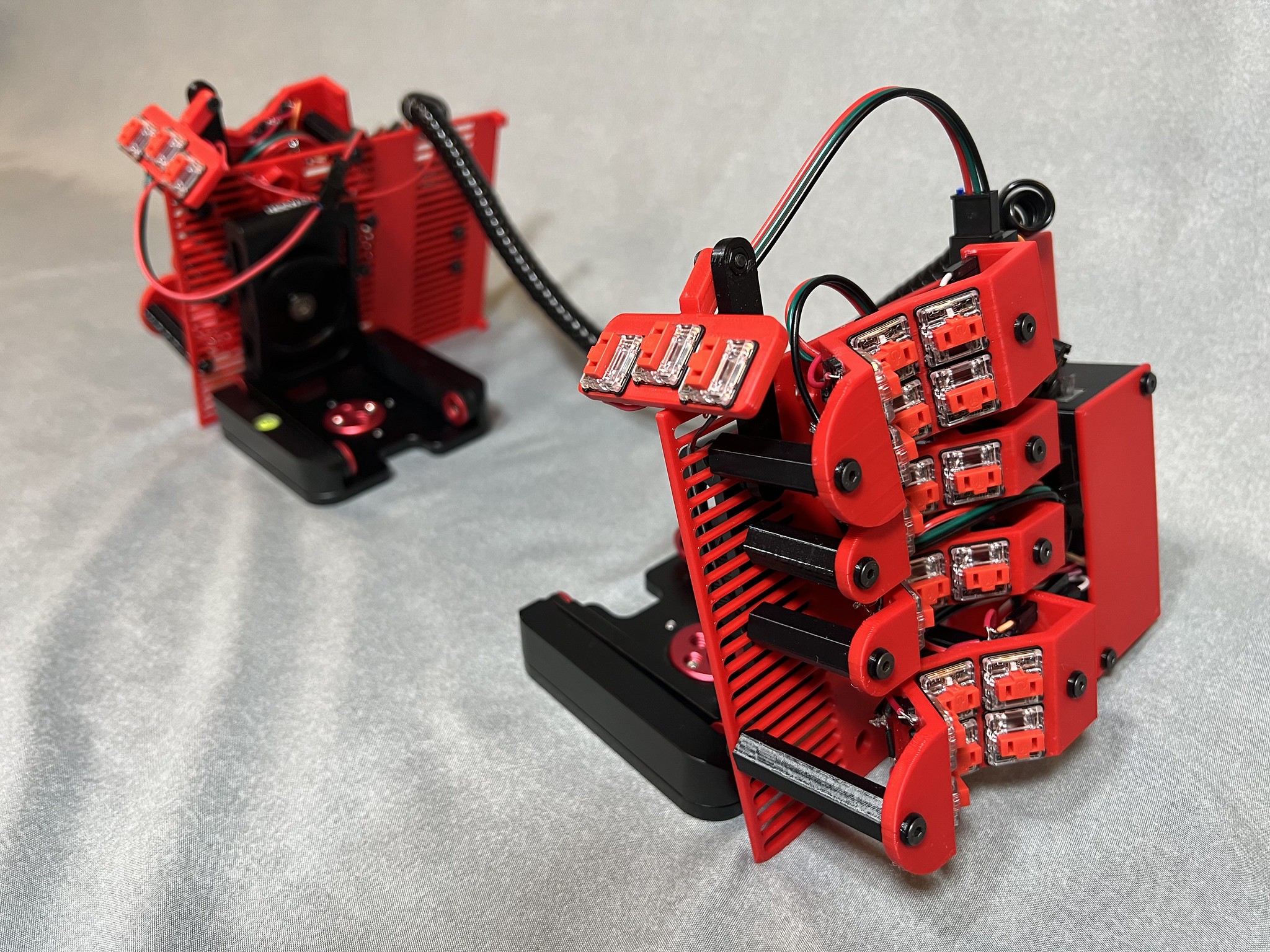
New thumb cluster post
Same basic mechanism of slots and bolts is used to attach the thumb cluster, but as it is oriented 90 degrees off from the fingers, it goes just on a post. I made the stem longer to allow greater range of motion on the open/close lid type action. I mount mine basically as low as the base plate will allow and that ends up feeling about right for me. The center of the thumb plate ends up about aligned with the base plate of the main keyboard, so there's one key inward from home and one key outward.
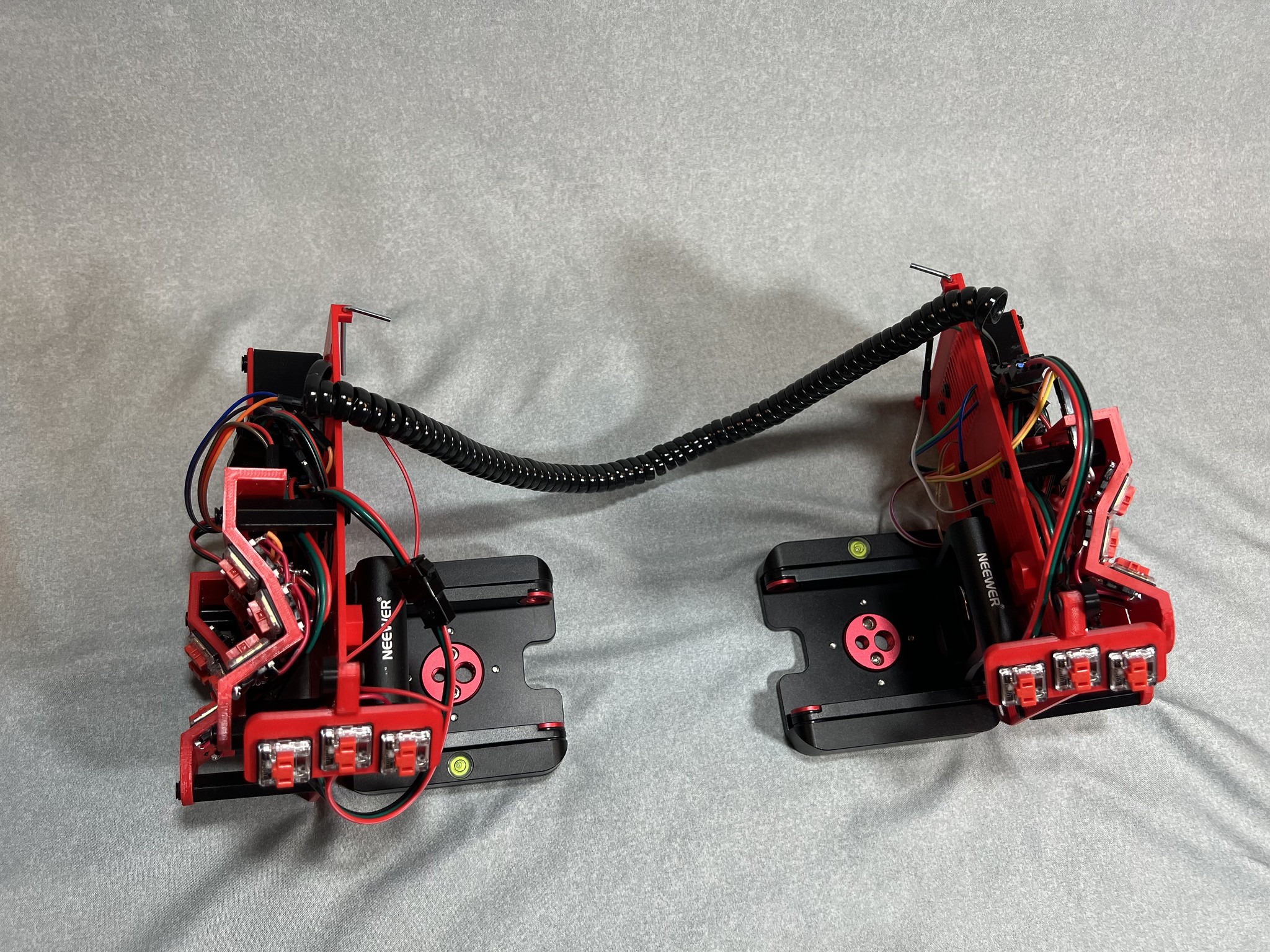
Base plate camera mount
The base plate has a housing where I've glued a standard 1/4-20 hex nut so I can mount this on my Neewer camera mounts and similar gear. There are 5 total positions to allow some experimentation with balance and stability but for me dead center seems to be OK.
Base plate hex wrench holders
The base plates have a little slot where I can store a hex wrench for adjusting things. I got tired of losing track of the only one I had so I ordered like 20 of them and 2 can just live on the keyboard now.
New brain box
The Elite-C microcontroller, reset button, and RJ9 connector are housed in a custom designed box. This has a 2-tone lid which attaches with my go-to heat-set threaded inserts and M3 bolts. The brain box mounts to the base plate again with a pair of M3 bolts. The brain box is much improved over all earlier versions, but that bar was set really low. "Case? What case? The microcontroller is perfectly happy just flapping around at the end of some soldered wires.". That said, I remain terrible at remembering at design time that wires actually occupy physical space, so both in the case and outside of the case the wiring is super crowded and a pain in the butt to work with. But it's workable and the lid does close and everything can reach where it needs to reach. But the idea of like easily swapping in a different column is not easy. It's a lot of tedious mucking with hex wrench, bolts, tiny connectors, and very cramped places where fingers can't reach, so it's a pain. Now that I have it all built, I'm probably going to do some very small adjustments to columnar stagger for exact tailor fit and symmetry across the hands and then tighten down the bolts and try to not mess with it again if possible.
New wiring connectors
As with the previous version and explained in this video, each finger column is a standalone 3-key macro pad that can work entirely on its own when wired to the microcontroller. The keys connect up the 3 row wires in this version using 4-pin JST connector. I was excited about this during the thinking phase, and I like the nice secure connection these make, but they are just too bulky relative to the Dupont jumper wires I used in the previous version, so I probably will move away from these in futures designs. More on future designs below.
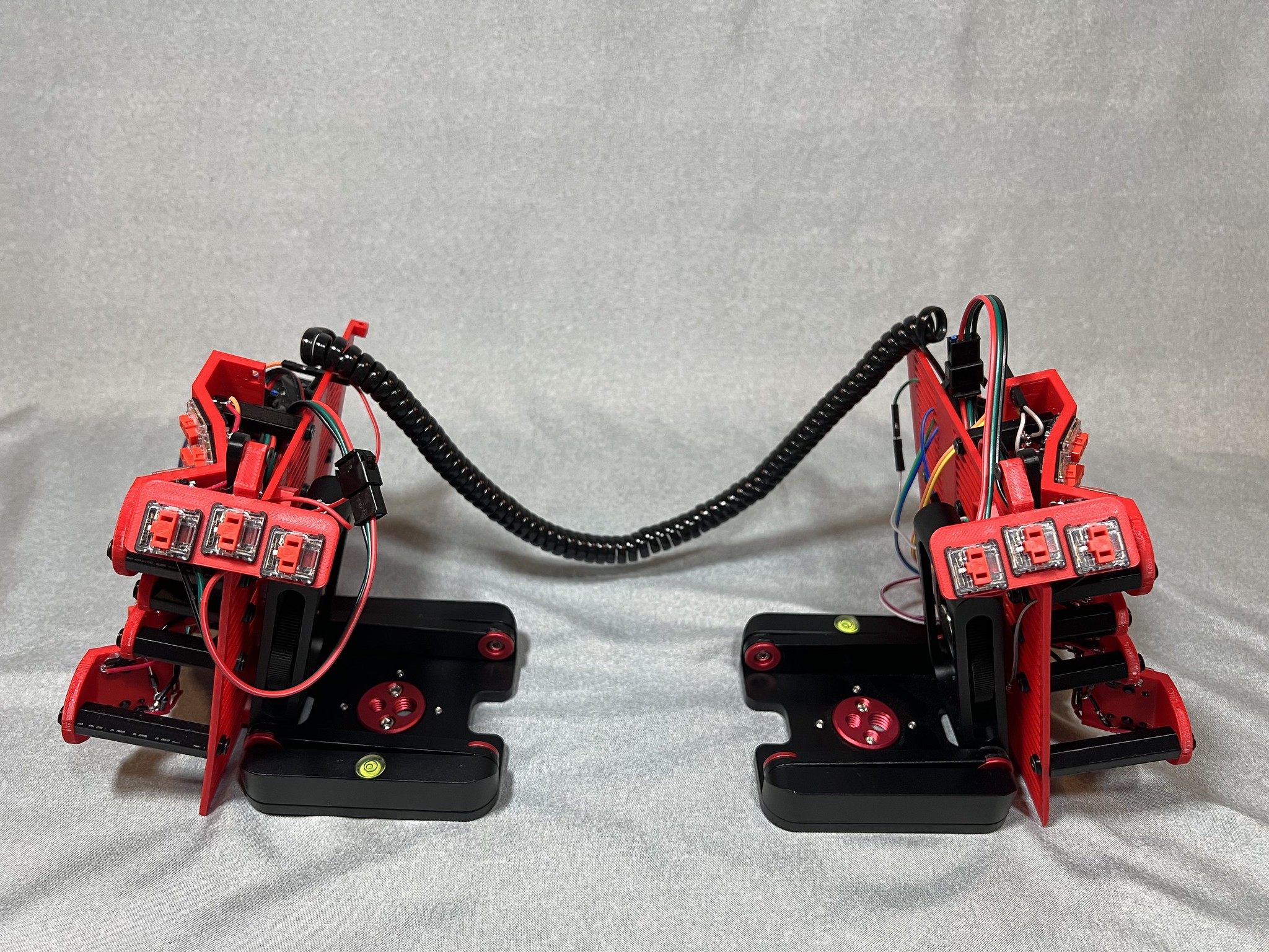
New wiring design
In the last build I wired the rows from pinky through thumb then to the microcontroller, which meant the thumb had both incoming and outgoing cables. To tidy that up, I now have a custom made Y cable coming out of the brain box and one side daisy chains to middle-index-thumb and the other side goes to ring-pinky side. It keeps the thumb a bit tidier in exchange for the cables near the middle finger being more crowded.
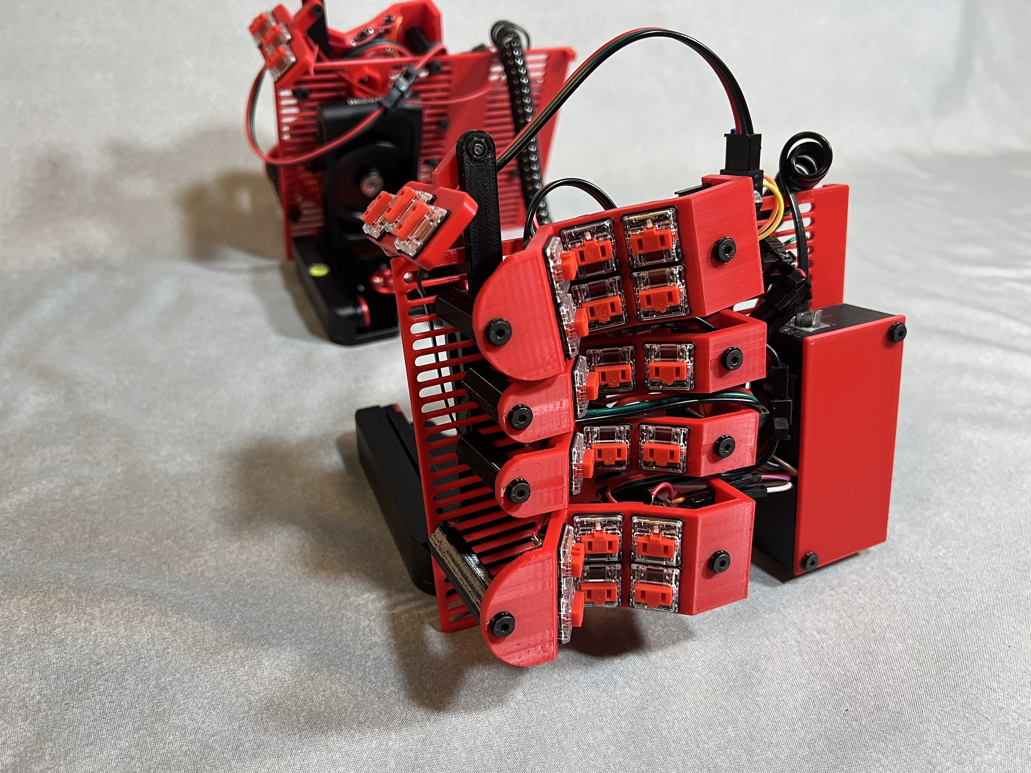
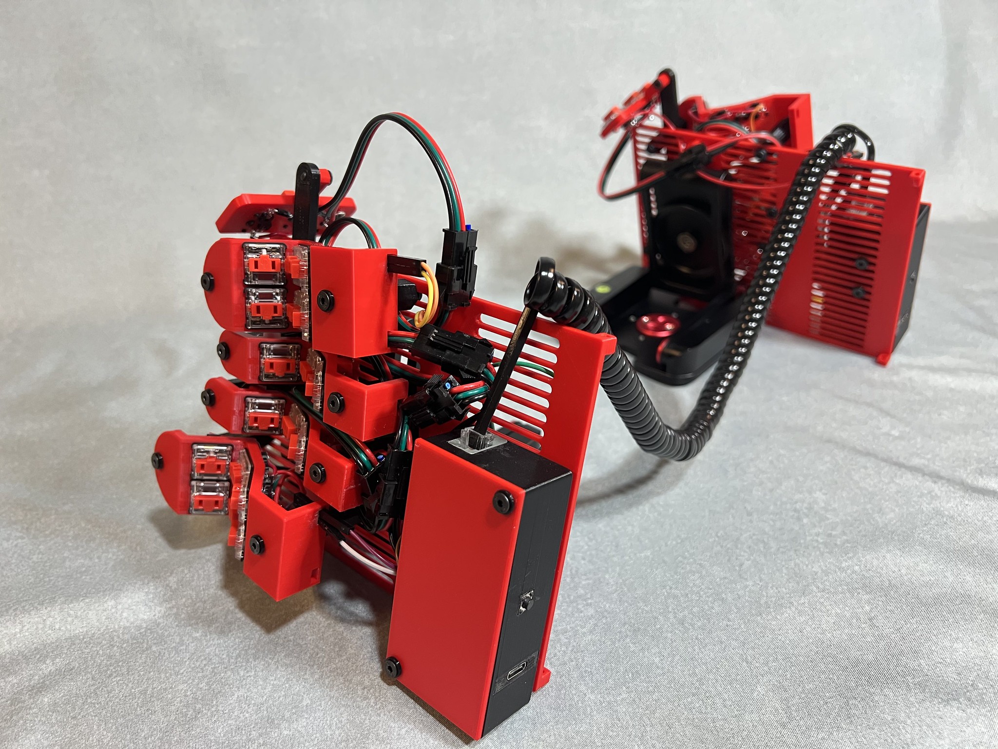
choc red color scheme
I switched back to Kailh choc reds for this and decided to print it in red and black PLA to match the switches. I'm really pleased with the look and it gives me that 80s TV "A-Team"/"Knight Rider" vibe. Let's be honest, this device will probably spend most of its life on my desk not actually being used, so at least it can be kind of pleasing and slick to look at. :-/
One more pinky column
My current daily driver is a TBK Mini which has 6 columns for the fingers, and although I'm trying to not use the pinky very much, that extra row does come in really handy and simplify layouts, so I added an extra column for the pinky to reach to. This also gives me better hope of switching to make the Squeezebox my daily driver since now it has exactly the same number of finger keys and the same thumb cluster arrangement as the TBK mini so all I have to deal with is the form factor switch itself but my keymap setup can be identical. So each hand now has a pair of 6-key double wide units (pinky and index), and a pair of 3-key units (middle and index) and a 3-key thumb cluster.
Files for 3D Printing
If you want to print one of these I have uploaded the files and instructions to prusaprinters here.
Notes and Learnings
I had a huge struggle and delay this time due to adhesive issues. I started out using Gorilla Glue brand Superglue Gel (cyanoacrylate or "CA glue"). The gel makes it reasonably achievable to get glue where it needs to go to hold the Kailh hot swap sockets onto the PLA part, but it takes way longer to cure than advertised and I don't really want to use accelerant from a spritzer bottle and get it over way too large an area when I really only want it on like a single square millimeter. I guess I could try like spraying accelerant onto a Q-Tip and then applying to the socket then putting it into place on the gel, but it's already a tedious process. Once cured, the superglue does not hold well. The sockets were popping off like mad, especially if the key column flexed at all. I probably had to re-glue at least 10 of them.
So I tried Loctite 2-part epoxy but also had issues. It took forever to cure as well, like more than a day, and even then it was still visibly gooey. I live in a very cold and humid climate, so it may be challenging conditions for adhesives in general. But it's also a pain to get a small amount mixed, emits a lot of nasty fumes, suggests you waste a mixing nozzle for every application which I don't really like. All I can say is epoxy cures clear and looks tidy relative to superglue, which cures to crusty ugly white and can really ruin the appearance of an otherwise stylin' part.
I may try to add some walls for the hot swap sockets to the 3D model so it will have a floor, 2 post holes, and 2 walls to hold it as well as more surface area to glue, but that's going to introduce bridging to a part of the print that is high precision and a little sagging there will prevent the socket from fitting so I'm not sure. I might just give up on hot swap sockets. They are neat and it's cool to list hot swap as a feature, but realistically I'm not going to be hot swapping switches and they add a lot of complexity to the CAD and assembly and soldering so I'll likely just ditch them and run soldered wires from the switch pins to a PCB with a dupont connector in future versions.
Another design goal that did not work out was I intended for each key column to have a "port" like a store bought piece of electronics so I was going to glue the JST female connectors firmly to the front of the column (that's the entire reason the columns have a "nose" part at the end) but I couldn't get any adhesive to bond strongly enough for that to work out. I got it kinda working for the dupont wires on the double wide parts but on the single wide parts I ran into an unforeseen collision between where the standoff post mounts and where the dupont connectors would be so I had to abandon that feature and just mostly have small wire connectors dangling off here and there. That makes the wire splices even more prone to failure.
I was inconsistent with remembering to use heat shrink tubing to insulate and support my wire splices in this one and I think it helps a lot, so I'll try to remember to do that more consistently. After the initial build I broke 2 wires at splice points during assembly. The 2nd custom Y cable I made I did it and it came out pretty nice. Generally my splices have large solder blobs as I'm not good at it, so I need heat shrink tubing of much higher diameter relative to the wire I'm splicing.
Next version plans: Custom PCB
So now that I've done all these iterations, I can see how this could evolve to a hybrid partially hand wired but mostly using a printed circuit board.
- I'd not put any diodes on the key columns. Instead, I'd use surface-mounted diodes on the PCB.
- Each column would get the following solders/wires
- A wire from one of the switch pins on each switch to the PCB, which will then go through a diode (the row wires)
- A wire connecting each of the other switch pins together (the column wire). This then routes to the PCB and on to a microcontroller pin.
- The PCB would be designed to take the place of the 3D-printed base plate. I think PCB material (which I gather is called FR4) is sturdy enough. It's probably much more rigid than this print which is only I think 2mm thick.
- Behind each switch column would be through hole connections, 4 per column. 3 for the rows and 1 for the column.
- The rows all connect across to each other and then on the pins on the microcontoller
- The columns route directly to the microcontroller
- A standard Elite-C through hole housing, probably still on the far side roughly where the brain box is now
- Reset button is easy and can go kind of anywhere
- 3 through holes for wiring the RJ9 for inter-hand connection
I think that's it. That would enable me to bundle the 4 wires from each switch column into some heat-shrink and make it pretty tidy, while still allowing mechanical repositioning of the columns and removal/replacement independently.
Anyone want to teach me some kicad? I've never designed a circuit board.