Kipra Keyboard
TL;DR (This post is over 4500 words. Sorry. Not sorry.)
I made a split ergonomic keyboard called the kipra v1 using a generator tool called ergogen.
Introduction
I've built a new split ergonomic mechanical keyboard called the "kipra". My daily driver for most of the past year has been a sofle choc, which is overall quite good and adequate for my current needs. However, I wanted to make something even more tailored to my specific preferences in terms of features and hand shape. The sofle was kind of bought on a whim when the vendor had a business closing sale so it had a bunch of stuff I wouldn't choose starting from scratch.
Requirements
After going pretty far toward the end (beyond the end?) of the distribution for custom scooped and tented split keyboards, I was in the mood for something much more portable, durable, replaceable, and generally pragmatic. Tenting is a real pain for this, and I have been using my sofle flat for a year with no RSI pain, so I felt confident I could abandon tenting at least for now and hope I stay pain-free.
I also wanted the thumb arc way lower and further inward than almost any other keyboard I have seen. I find tucking my thumb under my palm quite uncomfortable and I don't understand why so many designs put thumb keys under the palm. So I wanted my innermost thumb key just at the edge of my palm and an arc away from there. I also like to thwack my thumb keys with my thumb knuckle, not the tip, so positioned the thumb arc accordingly.
I wanted dedicated modifier keys. I have tried home row mods and all the tweaking to try to make them work and I don't like them. I type using the dvorak layout which has tons of rolls on the home row and that makes home row mods even trickier. So 4 dedicated modifier keys per hand. I also wanted to try putting the modifier row at the bottom vs my sofle layout which has them on the top row. Mods on the top row requires shifting my whole arm and losing home row, but I can curl my fingers enough to reach the bottom row without a full reposition so I think it will be better, but time will tell.
I don't want a pinky reach column as it's an RSI risk, so I eliminated that column entirely in comparison to my sofle. I also think I can handle function keys as tap-holds on my numpad layer, so that's a whole row I don't need also.
I didn't want anything fancy or fragile. Just the basics. No rotary encoders, no LEDs, no screens, no pointing devices, etc. Just a basic keyboard I could rely on and toss in a bag without snapping any parts off.
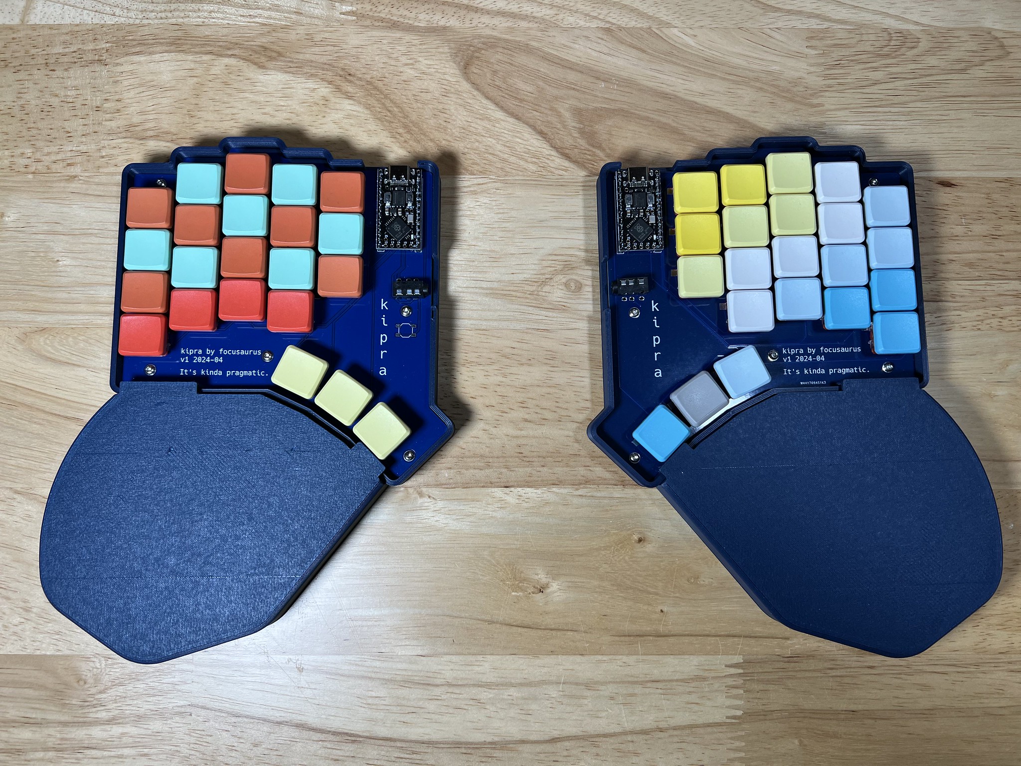
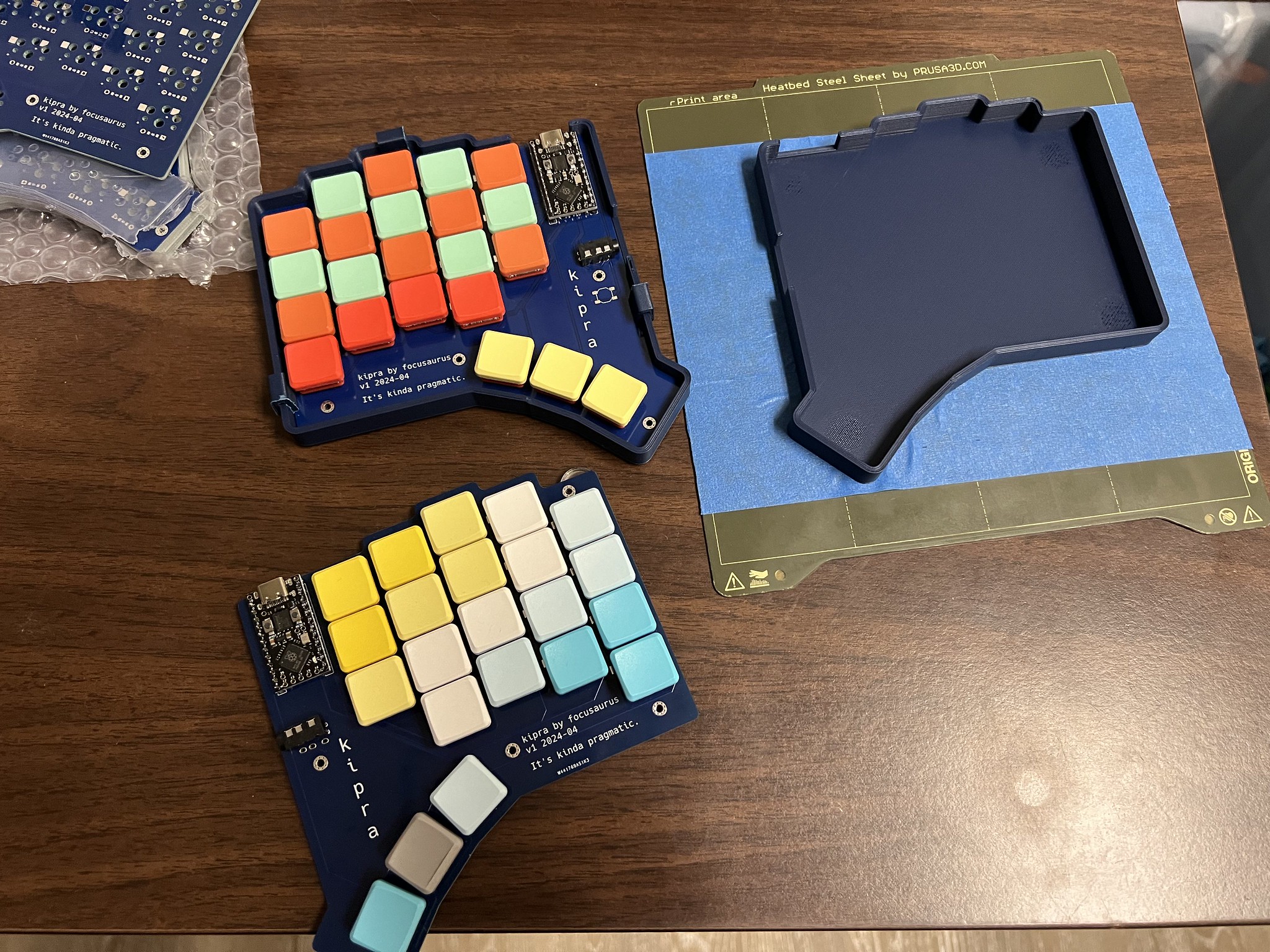
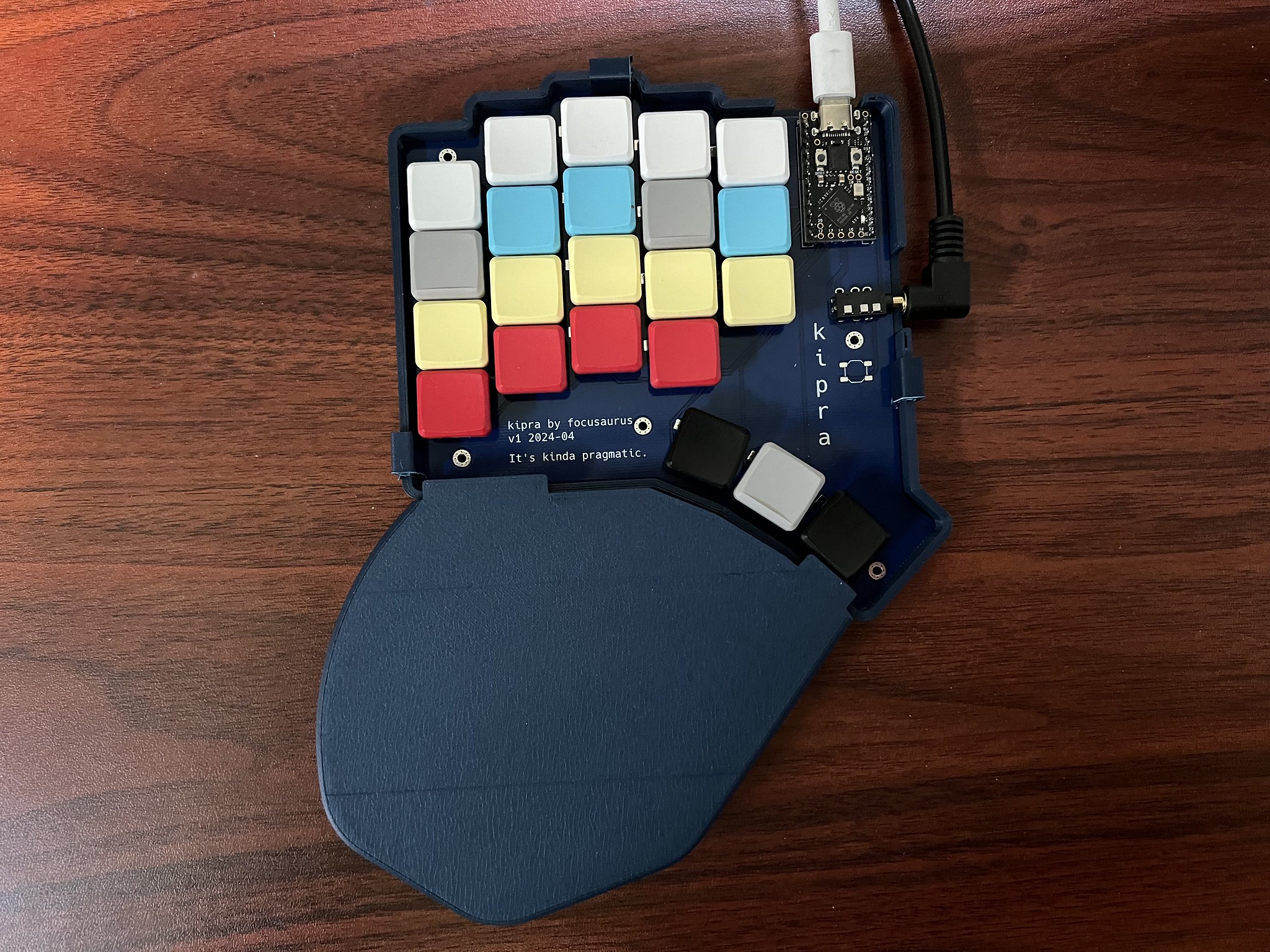
Thus I introduce to you The kipra keyboard: It's kinda pragmatic.
- Use a PCB and have the keys on a flat plane
- Nothing but switches
- Don't bother with any tenting
- Add a few extra keys to solve the modifier problem
- Make it wired so it's reliable
So in summary:
- split with column stagger tailored to my finger lengths
- choc switches with minimal vertical spacing and just a bit of horizontal spacing
- main finger grid is 5 rows by 3 columns
- below that are 4 dedicated modifier keys
- 3-key thumb arc
- PCB needs only 3 distinct electronic footprints: switches, MCU, and TRRS
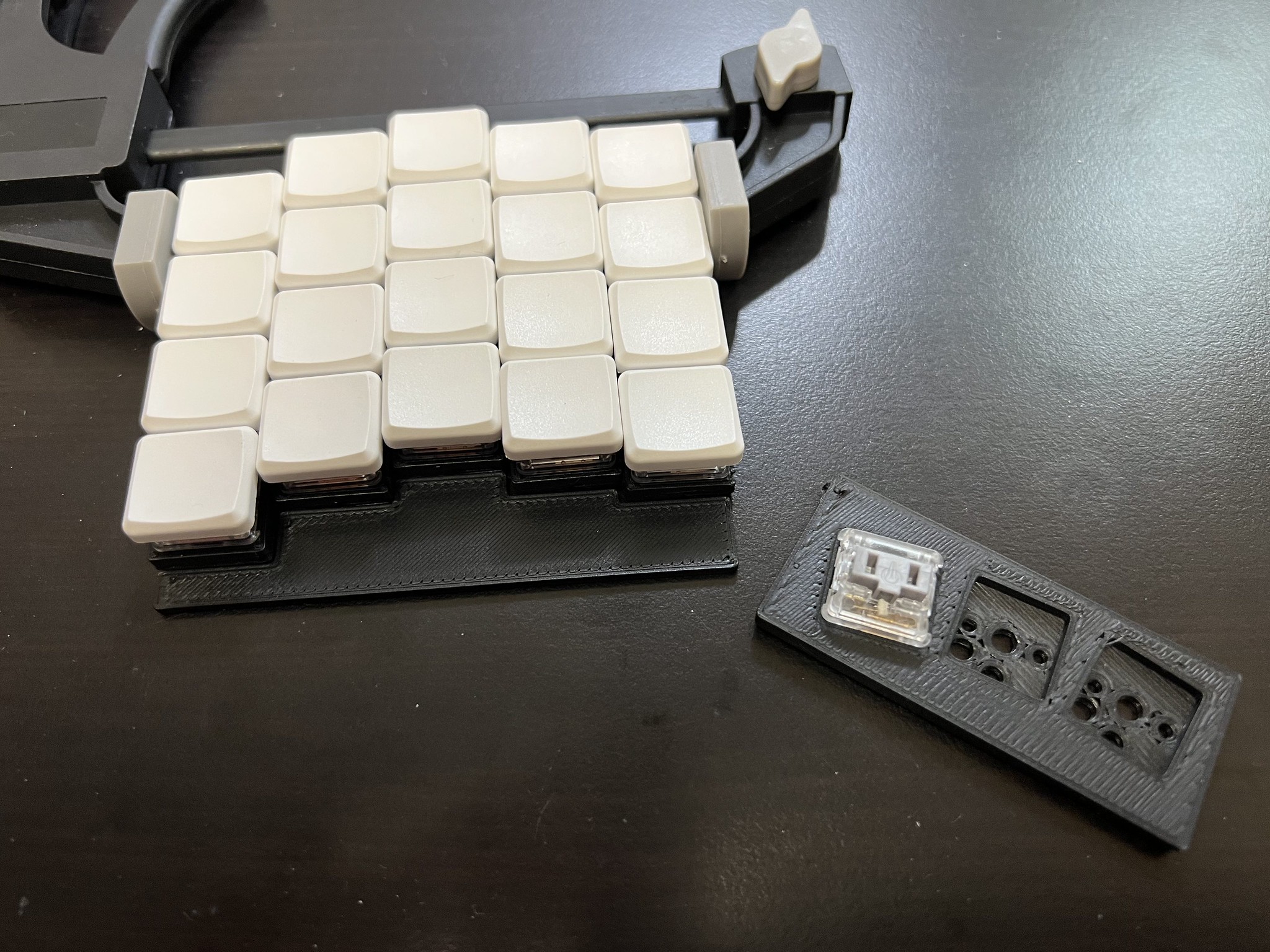
Preliminary physical physical prototyping
I printed up some 1x4 columns of switch housings and a thumb arc so I could test my column stagger positions and figure out exactly where I wanted my thumb arc. This will give me some confidence before I get PCBs manufactured, but it's never a guarantee. Things feel different when your actually typing on a working keyboard (spoiler alert for later!). But since this is mostly small tweaks to my daily driver sofle choc, I feel pretty confident this will be at the very least as usable as that is.

Designing with Ergogen
I used ergogen for this build. It's pretty easy to go from nothing to damn near a full keyboard in a single sitting. Here's where I was after the first session in ergogen.

Oh yeah, this was like back in August 2023. Project was mostly squeezed into the margins of my life over the ensuing 8 months.
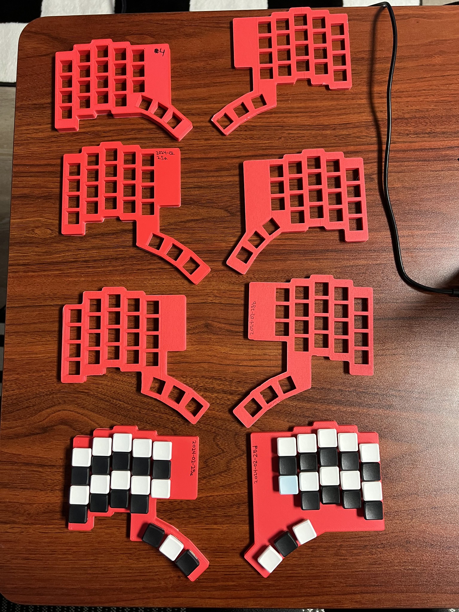
Printing accurate fit test prototypes
It's really fun to be able to layout the switches with some pretty simple yaml, then 3D print a mock-up that switches can be fit into and test out how it feels to type. Altogether I think I printed and did fit/layout testing across at least 6 iterations. The process consists of:
- Set up ergogen yaml for a rectangle for each switch footprint
- Add the overall outline of the edge of the PCB
- see the excerpt below
- run ergogen to output
build/outlines/test_print.dxf - In FreeCAD, start a new file and use Draft workbench
- Import the
.dxffile. It will create many shapes. - Select them all and hit the blue up arrow to upgrade them to wires
- Select them all and click the squiggly icon to convert to sketch
- Switch to Part Design Workbench
- Make a new body
- put the sketch in the body
- select the sketch and pad up 6mm
- 6mm is enough for the switch posts to clear the desk surface so the rig sits flat
- Export it to
.stl, load it into your slicer, and print it out - pop some switches in to test
The ergogen bit looks like this:
outlines:
  plate_shape:
    main:
      what: rectangle
      where: true
      size: kx
      bound: true
      fillet: 2
  switch_cutouts:
    main:
      what: rectangle
      where: true
      size: 13.8
  test_print:
    - name: plate_shape
    - name: switch_cutouts
      operation: subtract
This was in February 2024. I blame the holidays and traveling for that interval.
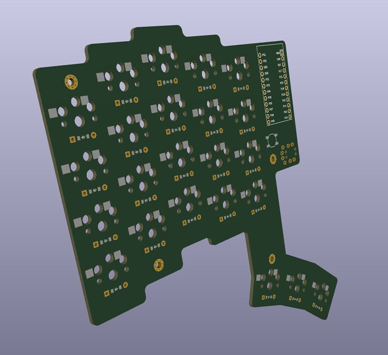
My first printed circuit board
I've built a few keyboard kits with their own PCBs, and done hand wired builds with no PCBs, but never had a custom PCB fabricated before. Luckily ergogen makes this overall pretty straightforward. You add the additional components, which for the kipra was just:
- a reversible MCU footprint for my pro-micro compatible MCU
- a TRRS jack
- a reset button footprint which I didn't end up needing because the one built into my MCU works great
- mounting holes for support posts
Ergogen sets up the electronics properly so your keyboard matrix is well-defined and the manual work you need to do in KiCAD to route the tracks is nearly foolproof because the Design Rules Checker will tell you if you forget anything, and KiCAD won't even let you wire something to the wrong place.
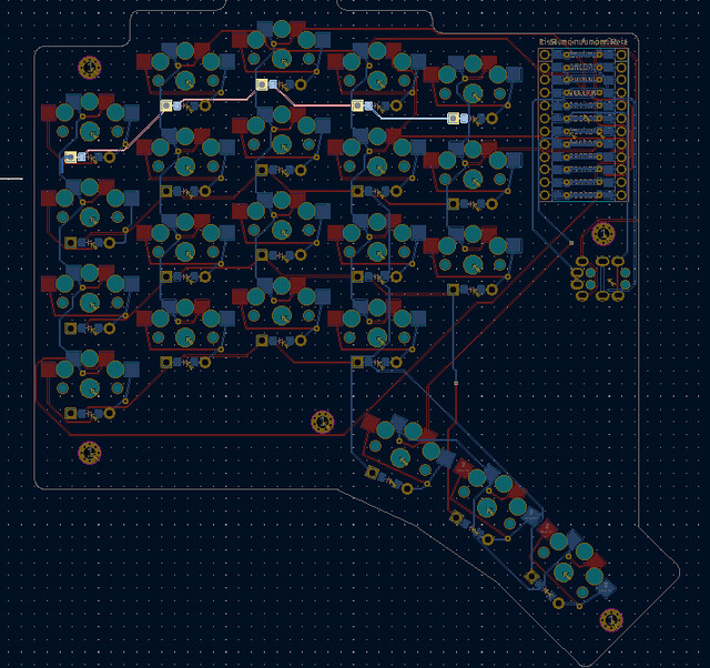
There's a tricky hand-off in the process where you've done all you can in ergogen and generated a KiCAD file which you then start to modify. If you discover any changes you want that require you to go back into ergogen, you'll need to re-do all the KiCAD work. So I put off routing traces for a while as I gradually ran out of tweaks to make in ergogen and started to get bored and keen to get on with the KiCAD bit.
It took a while for me to learn KiCAD and get the track routing done. I didn't know about "nudge mode" in the track tool until I paired with someone from Recurse Center who told me about it and then things were a lot easier.
I was super nervous about having a mistake in the KiCAD manual work that would render the PCBs unusable, so it took me a long time and lots of re-dos to practice and get slightly more confident that everything would work. The reversible PCBs can be mind-benders when things get tricky. I also used a fancy reversible MCU footprint which was important since I wanted both of my MCUs mounted face up so the buttons were accessible. Many footprints require one or both of the MCUs to be mounted face down to get the pinout to align properly on both halves.
I got a lot of help and checking, but eventually the Design Rules Checker in KiCAD had no errors and it was time to generate some gerber files and upload them to PCBWay for fabrication.
Fabrication with PCBWay
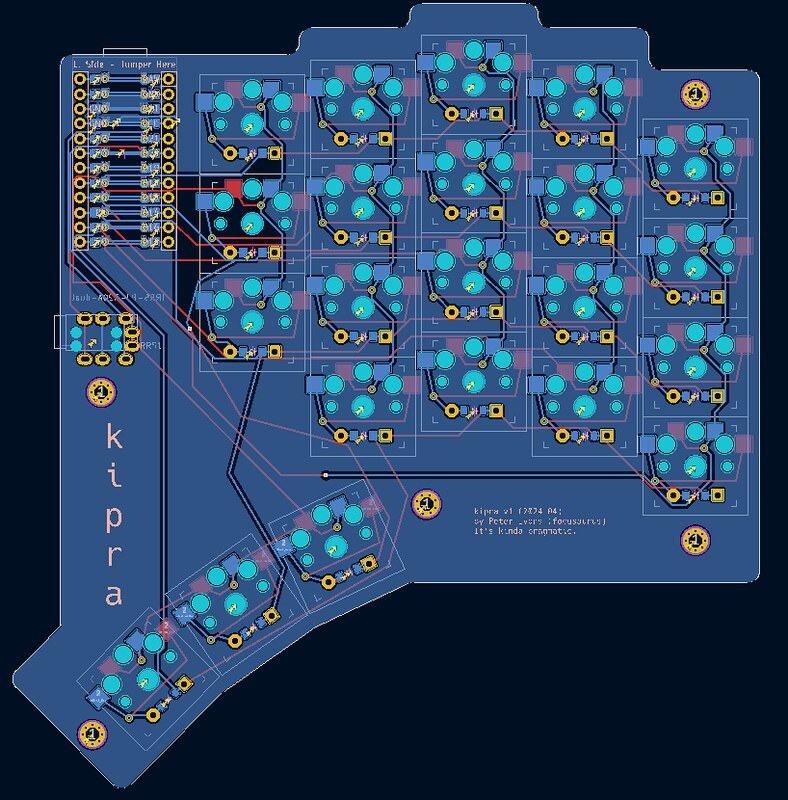
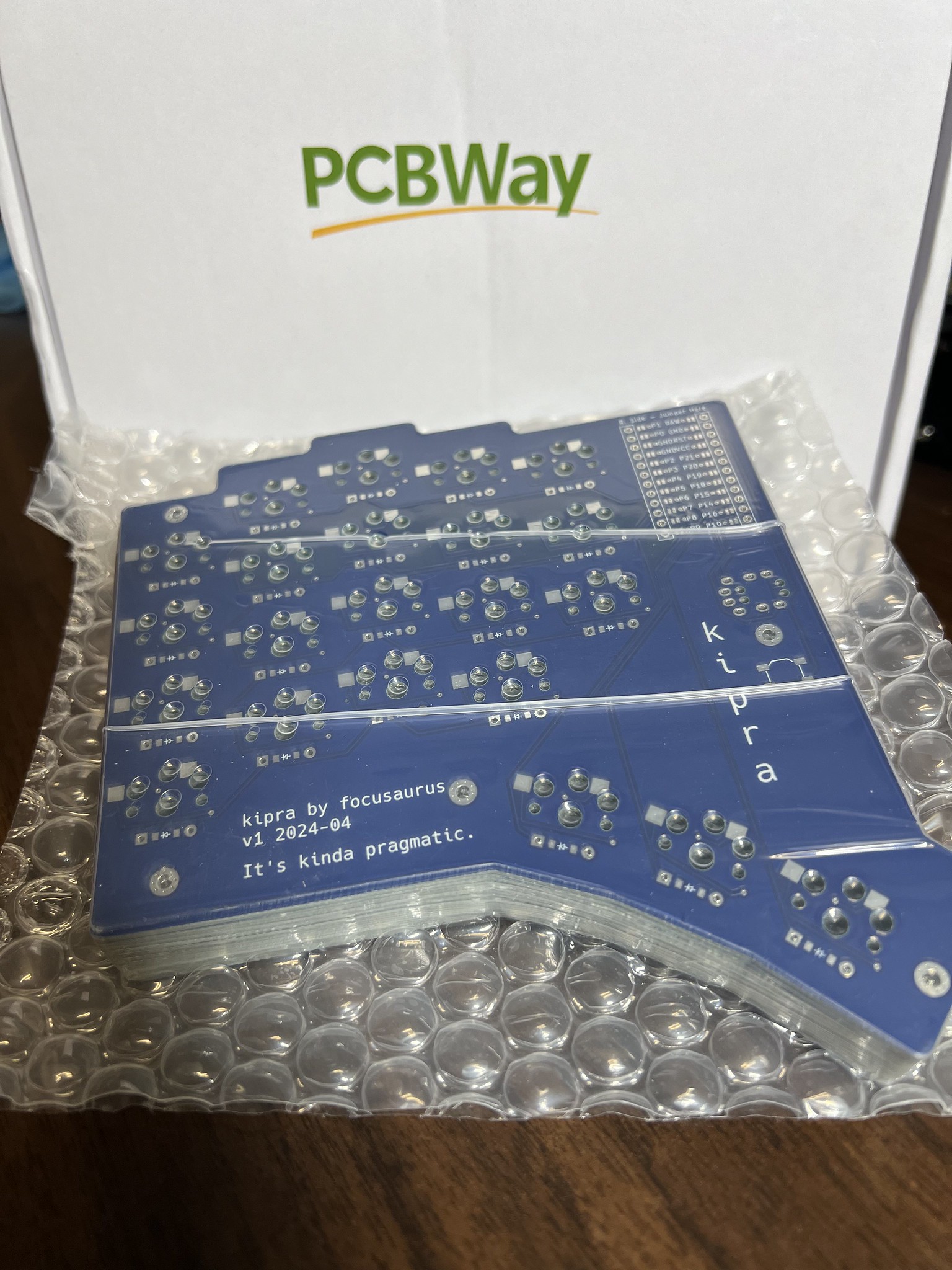
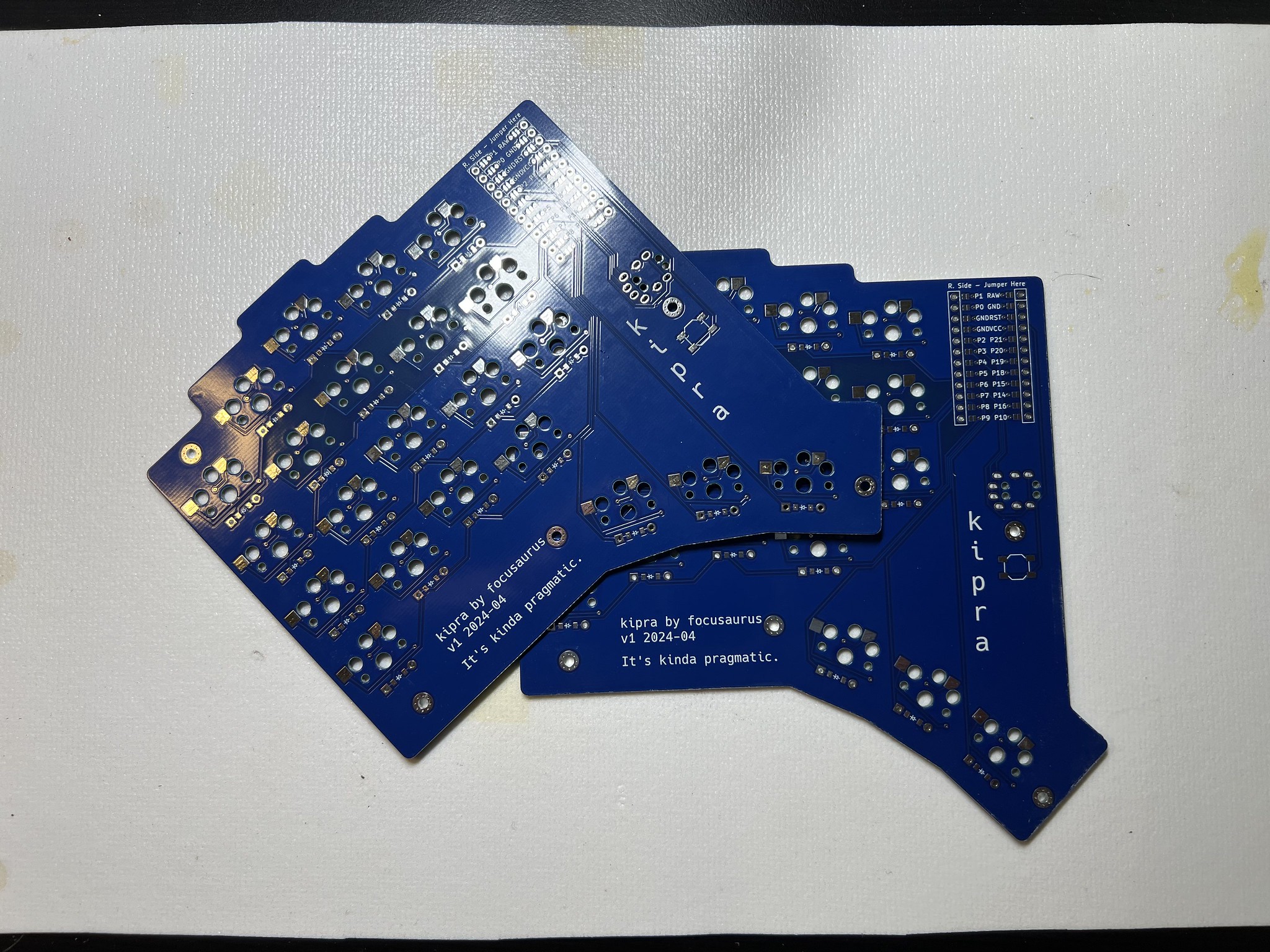
My friends at PCBWay offered to support this project so big thanks to them! I uploaded my gerber zip file, followed their documentation about using settings that would work properly, chose blue for my PCB color and white text set in Hack Nerd Font. Then I fired off an order for 10 reversible PCBs which can make 5 split keyboards. About 10 days later I had a package on my doorstep with a bundle of beautiful circuit boards!
Some custom text added in KiCAD
It's silly, but I am solidly at the place where having a PCB with bespoke silkscreen text in my hands still feels special and awesome. The charm will likely wear off in a few more builds, but I'm enjoying this moment.
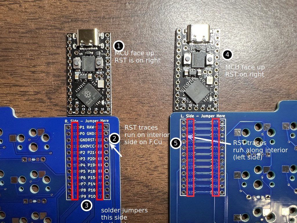
Soldering and the oh fuck cycle
Soldering the diodes, hot swap, and TRRS were familiar to me so I was pretty confident all that would work out correctly. But for this reversible MCU I needed to solder across pairs of jumper pads on the correct side, and due to wanting both MCUs facing up, I ended up having to do exactly the opposite of what the instructions on the PCB silkscreen said. So this contributed to many rounds of what I call the "oh fuck...whew cycle". This starts with me soldering something and then either thinking or being told on discord that I just fucked it up. Typically this kind of thing is all or nothing. You get all the MCU pins wired correctly and you have a keyboard, or you make one mistake and you have a drink coaster.
(The reality is not that stark especially if you do electronics work regularly, but in my anxious mind all this felt very high-stakes)
But each time within a few minutes and with posting KiCAD files or screenshots or photos, eventually we hit the "whew" phase of the cycle where we figure out actually it's fine and correct. Keep in mind this is a custom one-off project. It's not a kit that dozens (dozens of us!) have built before. So asking for help requires friendly folks on discord to go the extra mile to learn your custom design and provide guidance.
I went through a few rounds of "of fuck...whew" on the PCB jumpers, a few rounds on the MCU mounting, a few rounds on the MCU pinout, a round about whether I had been referencing the wrong pinout for the entire project (I had), and a few rounds on the TRRS QMK firmware stuff. Exciting times!
MCU mounting footgun
Mounting the MCU revealed that my MCU had one extra through hole per side compared to the footprint on my PCB. So I had to figure out if the extra empty hole was supposed to be the one closest to the USB connector or the one furthest away. I also had to snip one of my pin headers off to make it match the PCB footprint. I studied the pinout a bunch and tried to reason that reset should map to reset, etc, but it's tricky because my MCU footprint is reversible and has jumpers so everything is like "this is reset, unless you soldered one of these jumper pads, in which case it is no longer reset", but exactly how all that cleverness works out is really tricky to keep track of. This was extra fun because the microscopic hole labels on the MCU are mostly between the through holes and it's not clear if the label applies to the hole above or below the label, and even studying the ends of the row don't really clear it up. But in the end I was pretty sure I needed my rows and columns starting on the holes farthest from USB, so I mounted it that way, and it ended up being correct.

I also chose to NOT socket my MCU, flouting all the advice online. I've socketed a lot of MCUs and it's extra fiddly work and difficult to prevent the headers from bending. These days MCUs and PCBs are cheap, so I'm comfortable just using regular pin headers and not futzing with socketing.
BUT in the end it all worked out. No mistakes. No parts wasted. The first 2 kits I have built are fully working.
Whew!


RP2040 MCUs are great
For this project I had ordered some MCUs from aliexpress that were on sale for something under $4 each I think. These are pretty great.
- RP2040 chips which are great
- pro-micro compatible footprint which makes them usable in many existing kits/projects
- have an on-board reset/bootloader button which makes flashing super easy
I have to say my early forays into QMK in 2019 were traumatic in how much a fiddly pain everything about flashing was. I bought a bunch of terrible cheap promicros with micro USB connectors that were a complete nightmare to get to show up on the USB bus and to boot into the bootloader and to successfully flash without bricking them. I tried linux, windows, and mac and went on many extended docs/forum reading sprees. It was a nightmare of rapidly shorting pins with tweezers, no error messages, etc.
Even the stemcell MCUs I bought recently for the sofles were a giant confusing pain.
In contrast, these RP2040s are amazing. Hold the bootloader button while plugging in USB then release it. They show up immediately in your OS as a mounted thumb drive. To flash them you copy a .uf2 file to the root directory and that's it. The actual flashing requires zero special software, although compiling a firmware image still requires a working QMK toolset. They are fantastic.

The struggle to TRRS split
I got both halves of the keyboard working when directly plugged into the computer via USB fine basically on the first try with no errors. But I couldn't get the TRRS connection to work so the secondary half would type. I spent a day reading QMK's extremely-confusing docs about serial, i2c, uart, usart, pio and flailing around until clutch help on discord arrived to guide me through the exact right settings for config.h, rules.mk, etc. There were dozens of rounds of recompiling and reflashing both halves then carefully recabling and seeing yet again the right side did nothing. TRRS comes with the risk of short circuits so care must be taken to always disconnect USB before working with the TRRS cable.
I got some clutch help on discord from someone who actually understands what the RP2040 has built in and that most of the QMK docs are for older, less capable chips, and most of what I needed was default. Shout out to casuanoob! Oh and ALSO there was a super confusing MCU pinout off by one error. As discussed above during mounting and soldering, my MCUs have 1 more through hole per side than the PCB footprint has through holes, so that casts doubt into every "count the holes" step in the docs and creates confusion between the MCU and footprint docs. I later learned that I was studying a slightly incorrect pinout because my assumption that the product detail page on aliexpress is for one exact product. In actual fact, the exact same page sells several different MCUs with different pinouts. So for the entire project I had been referencing a pinout that was similar enough to correct to not be obviously wrong, but was in fact not correct for the exact MCU part number I bought. So the better part of a day's flailing ended with incrementing pin numbers by 1 in the firmware and both halves started working together properly!
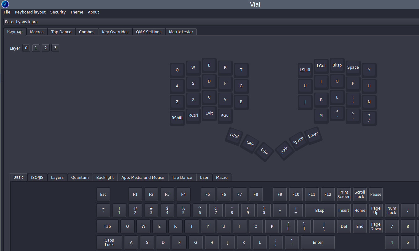
Vial configuration GUI for real-time remapping
While waiting for PCB fabrication, I got a head start on configuring QMK firmware and flashing my RP2040 MCUs. My goal was to have this board supported in Vial which is a nice GUI that allows real-time changes to your keymap without reflashing. As per the Vial docs, I started by making sure I had a stock QMK firware compiling, flashing, and working as a keyboard. I confirmed this by just shorting a row hole to a column hole with a jumper wire and seeing a letter get typed.
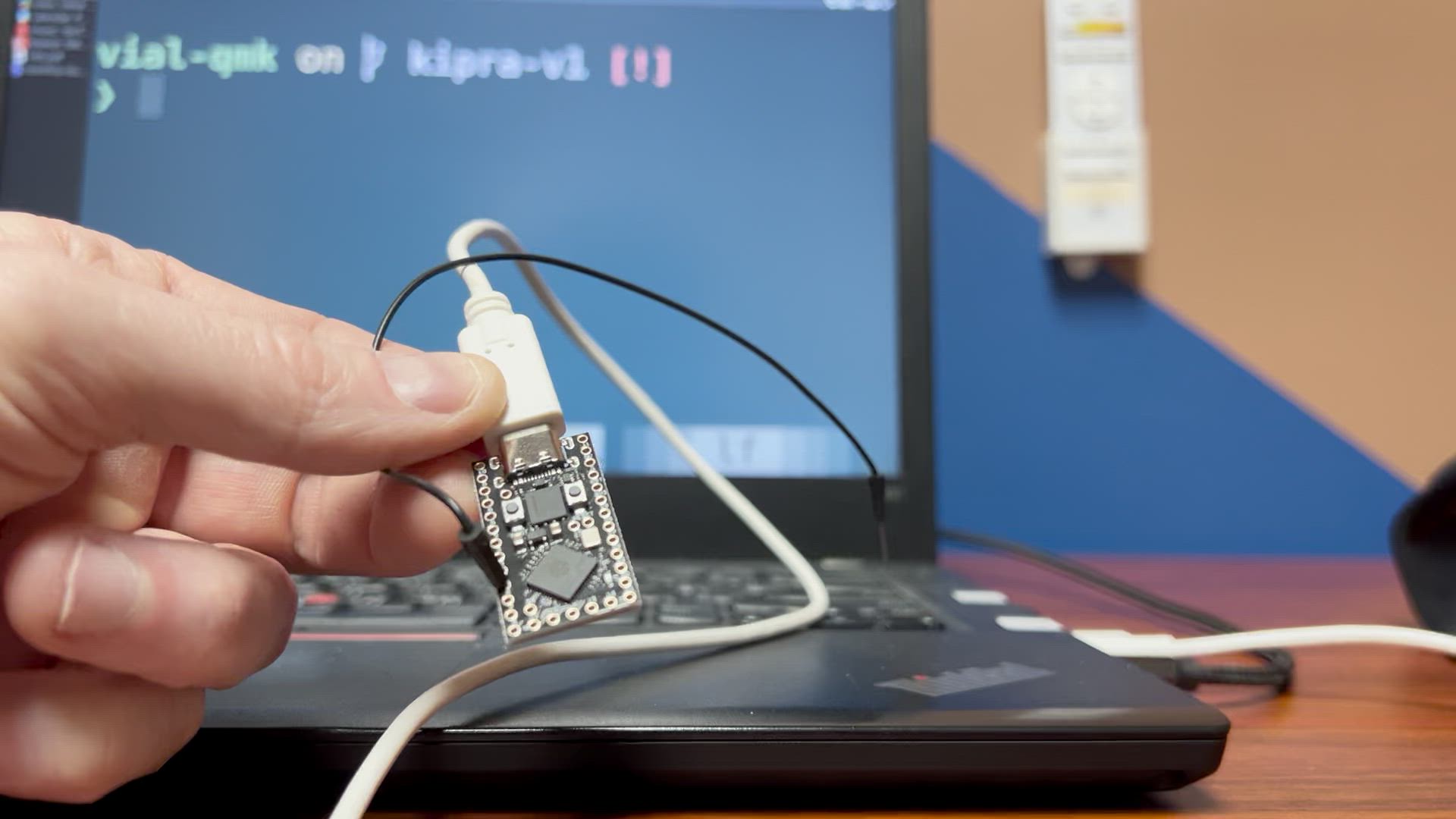
Then I ported my keyboard into Vial. This is fairly straightforward using the online keyboard layout editor GUI to specify your switch positions and mapping the matrix is mostly trial and error that's clear enough when you have things reversed by mistake. This is an approach I actually recommend for newcomers to the custom keyboard hobby: as soon as your MCU arrives, try to get it flashed and working as a keyboard by just dangling it off a USB cable and shorting a row to a column pin with a jumper wire. Much better to have this part sorted early. If things become difficult, this can require a level of patience and perseverence that are easier to muster at the start of a project.
So now I can change my keymap on the fly using the Vial WYSIWYG GUI which is great.
3D modeling the case in janky mode
As I understand it presently, ergogen doesn't provide that much to help with creating a case. I got it to spit out the basic outline of my PCB shape, but the rest of the process from the flatfootfox tutorial seemed daunting given the amount of geometry in my design. I also didn't have experience in FreeCAD with the Draft and Part workbenches which seemed to be essential to this workflow. But with a bunch of research and experimentation, I hacked something together roughly as below. I'm not sure I can even do this again because I tried so many sequences of workbenches and tools. But logically, the flow goes:
- start with the PCB outline from ergogen, imported into FreeCAD Draft workbench as a
.dxffile - Create a 2D offset from that allowing roughly 0.4mm for clearance so the PCB fits inside
- Then do another 2D offset at 2.4mm for wall thickness (4 perimeters with my 0.6mm nozzle installed)
- Select the
fill the offsetoption on this one so you get a face
- Select the
- Extrude that up 12mm. We now have a wall our PCB will fit beautifully into, but no floor
- Upgrade the first offset (where the floor should meet the interior wall) to a face and extrude it up 2mm
- We now have walls and a floor
- Use some standard geometry cubes and boolean difference in the Part workbench to make cutouts for the USB and TRRS cables
- I did this very crudely so far
- Ideally I would make 4 13mm diameter (not radius!) by 2mm depth cylindrical cutouts in the bottom for rubber bumpers at this point, but I was mostly winging this and so excited when I got something working that I ended up doing those in Prusa Slicer instead.
- Combine those shapes into a mesh and export to an STL you can print
The case is essentially exactly what I hoped for but it's a bit janky because I'm just eyeballing the MCU and TRRS positions since I have no reference geometry from ergogen available in this toolchain.
I would also ideally model the support posts exactly underneath the mounting holes in the PCB. These will get m2 threaded inserts. But I don't have a good process for this from ergogen, so I have decided to model individual posts, print them individually as distinct objects, screw them to the PCB, then just glue them to the floor of the case. I've tried to 3D model these without exact positioning information before and there's no fudging it. If you're off by a fraction of a millimeter, the bolt won't thread into the insert.
I did several attempts using threaded inserts with no success. The 3mm thickness is not enough material to properly bottom out the heat-set insert and not warp the entire thing so it won't sit flat. It's super easy for the threads to fill with molten PLA during inserting so the bolt won't thread. I did about 4 attempts before pivoting.
The next version I made little 3mmx7mm rectangles with a cutout to hold an m2 hex nut. So I just threaded the stack of bolt, PCB, printed standoff, and hex nut. Then I put a dab of superglue on each side of the bottom of the standoffs and set the keyboard in the case with some weight to hold it down while the glue cured. There's 5 standoffs and not much force so I think it'll be fine to keep the PCB in the case and also not have it resting on the hotswap sockets.

Adding Palm Rests
I have been using my sofle without palm rests comfortably, but the novelty of the kipra and the very different placement of the thumb arc made me feel like palm rests might be ergonomically necessary. I have some store bought cushy ones that actually fit nicely, but I don't like how they can slide around independently from the keyboard. Since I had a FreeCAD sketch of the case outline, I modeled some palm rests to mate up exactly to the edge of the case. I put some clips on them so the easily clip on then won't drift away from the keyboard.
I did 2 iterations so far and there's still more tweaking to do. The shape is still not quite ideal and I'd like to maybe add magnets, but these are workable for the moment.
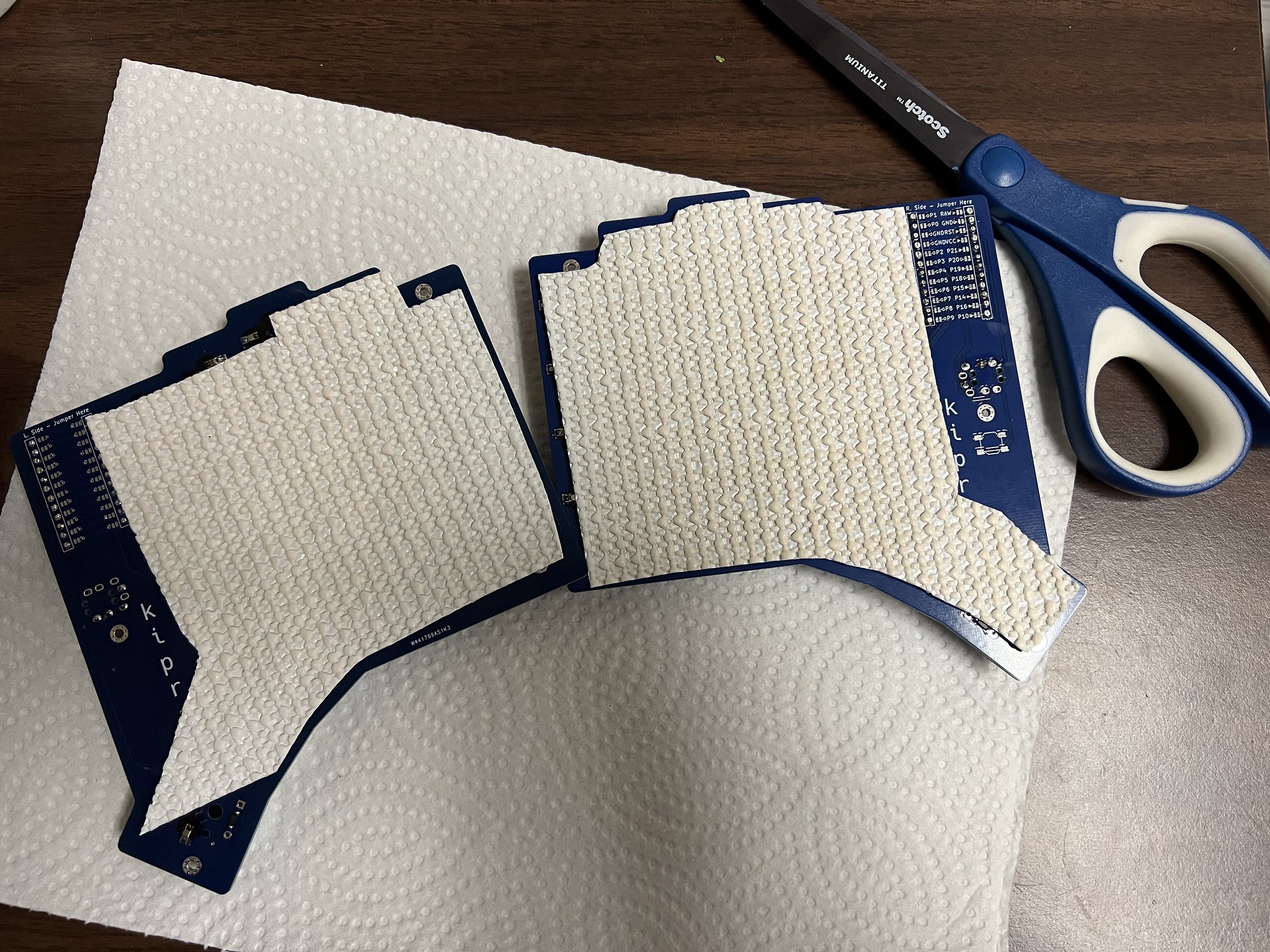
Removing palm rests and going caseless
After a few days of trying some variations, I thought I might be able to get away without a case, and hopefully without a palm rest, by attaching some shelf liner material directly to the underside of the keyboard. I cut some scrap pieces we had lying around to roughly the right shape, spritzed the interior side lightly with water which the gorilla glue I used needs to activate, put the tiniest partial drop of glue I could manage in the center of each hotswap socket, placed them together, and left them weighted overnight for the glue to cure.
I love that this is very low profile, provides some shielding for the contacts on the PCB, and provides enough friction to keep the keyboard steady on the desktop. I'm still testing but I think this approach might be OK, or possibly with a fairly low palm rest.
I later covered the exposed contacts with some electrical tape. I'll still need to make a travel case but all I need to figure out is some kind of lid mechanism.
Hoping for firmware bliss
My sofle has some nuisances that I suspect are either firmware or MCU issues. The one-shot shift key has a bug that makes it a 2-shot if you roll 2 letters quickly, which I do constantly starting sentences with "The" and it's a nuisance. Also the right half goes comatose somewhat regularly and needs a reset. Also my one-shot layer key stops working for 2 specific keys after a while which is bizarre. Actually debugging those I think would be pretty tricky, so I'm hopefully these new kipras don't have those issues. So far the evidence is that the 2-shot mod bug seems to still be there but the other issues are gone.
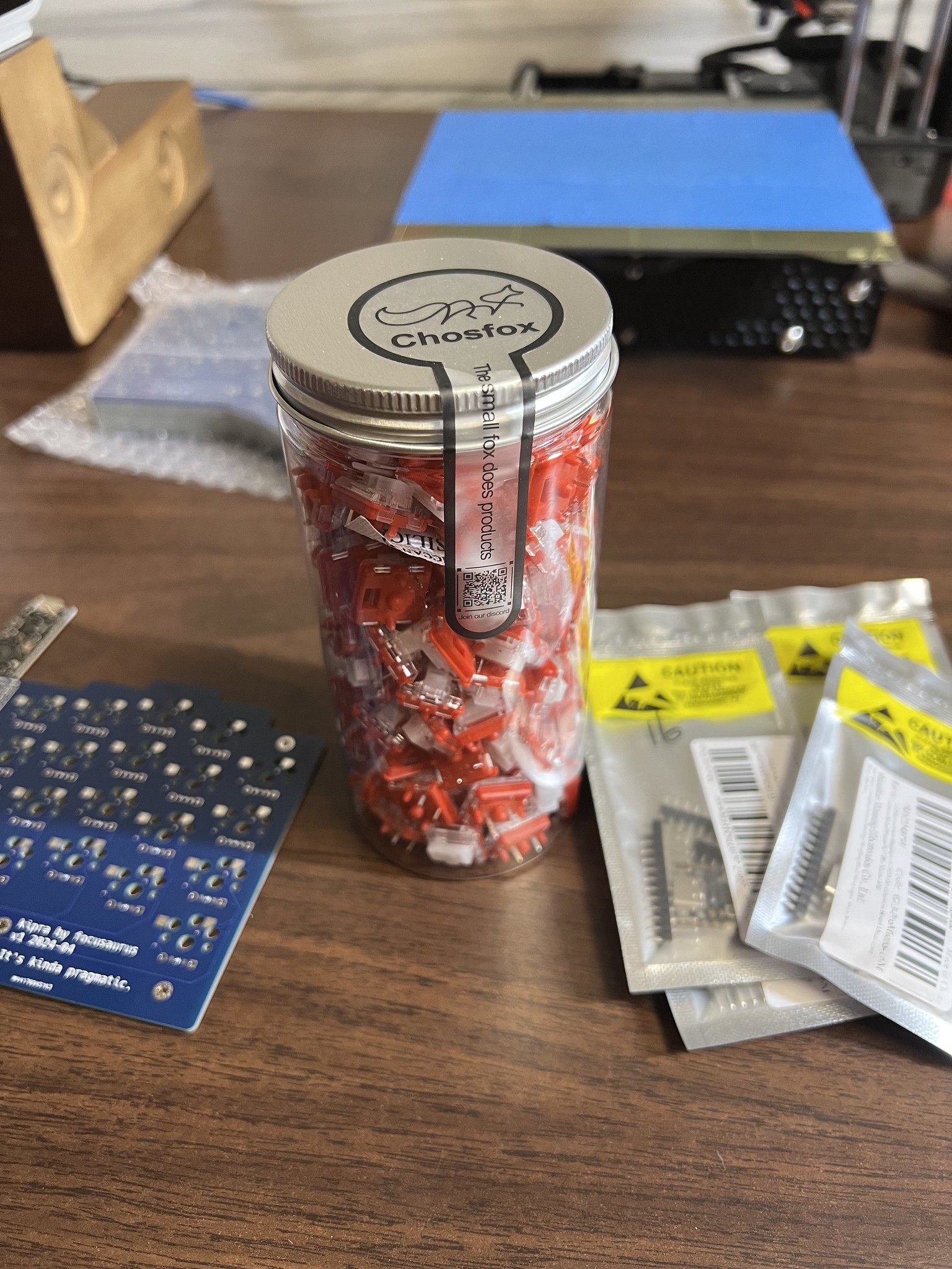
Ambient choc switches a few days too late
For these builds I ordered mostly enough choc pro red linear 35g switches to build 5 split keyboards. This was on April 5, 2024. On April 23, a brand new flavor of choc switches engineered to be silent went on sale for the first time over at lowprokb.ca. Of course I found out about this project just a few days after placing my order. Sad trombone.
But anyway, I ordered enough ambient nocturnal (20g linear silent) and ambient twilight (35g linear silent) for a keyboard each and they are amazing! Absolutely the nocturnals are my favorite switch by a wide margin. They are even quieter than my thinkpad or macbook laptop switches. I commented on /r/ergomechkeyboards that typing on them feels like whispering and like my brain thinks a word and my fingers create it automatically. With louder switches it feels like I have to strain to enunciate my typing "speech" to be heard. I love this intimate feeling they have and the silent operation feels almost magical.
Source files repo
See focusaurus/kipra-keyboard on github for all the files you need for ergogen, kicad, freecad, and PCBWay if you want to make a variation of this.
Build guide coming soon
When I built the second kipra, I took photos throughout the process so I could create a detailed build guide. This is probably mostly going to be for me to reference, but if anyone else ends up ordering some PCBs, this will help them get it soldered up correctly.
Thanks to my internet heros
I definitely could not have ever done this without both the cool open source projects people have built and shared, some online tutorials, discussion forums generally, and of course specific personal help for me with my many questions and struggles.
Special thanks and shout outs to my buds:
- mrzealot who is the lead on ergogen and moderates the Absolem Club discord
- flatfootfox who wrote this amazing in-depth ergogen guide which I studied constantly throughout this project
- ceoloide who designed the reversible MCU footprint and provided tons of detailed specific help to me to get this build designed and working
- causuanoob who diagnosed the QMK split keyboard firmware issues and helped get my RP2040 settings correct so the right half started working
- hand_le for expert guidance and troubleshooting help
- Jessie Grosen and Charles Eckman for the KiCAD tutorial and pairing
- All the QMK contributors
- All the Vial contributors